Chapter: Communication Theory : Amplitude Modulation
SSB Transmission
SSB TRANSMISSION:
There are
two methods used for SSB Transmission.
1. Filter
Method
2. Phase
Shift Method
3. Block
diagram of SSB
ü Filter Method:
This is
the filter method of SSB suppression for the transmission. Fig 1.3
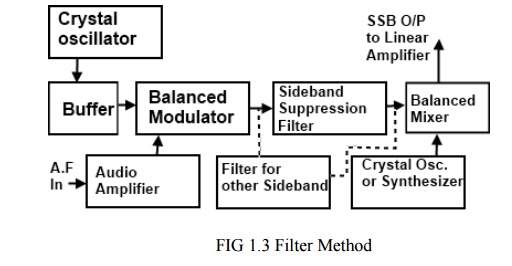
1. A crystal
controlled master oscillator produces a stable carrier frequency fc (say 100
KHz)
2. This
carrier frequency is then fed to the balanced modulator through a buffer
amplifier which isolates these two satges.
3. The audio
signal from the modulating amplifier modulates the carrier in the balanced
modulator. Audio frequency range is 300 to 2800 Hz. The carrier is also
suppressed in this stage but allows only to pass the both side bands. (USB
& LSB).
4. A band
pass filter (BPF) allows only a single band either USB or LSB to pass through
it. It depends on our requirements.
5. This side
band is then heterodyned in the balanced mixer stage with 12 MHz frequency produced
by crystal oscillator or synthesizer depends upon the requirements of our
transmission. So in mixer stage, the frequency of the crystal oscillator or
synthersizer is added to SSB signal. The output frequency thus being raised to
the value desired for transmission.
6. Then this
band is amplified in driver and power amplifier stages and then fed to the
aerial for the transmission.
ü Phase Shift Method:
The
phaseing method of SSB generation uses a phase shift technique that causes one
of the side bands to be conceled out. A block diagram of a phasing type SSB
generator is shown in fig 1.4.
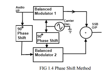
It uses
two balanced modulators instead of one. The balanced modulators effectively
eliminate the carrier. The carrier oscillator is applied directly to the upper
balanced modulator along with the audio modulating signal. Then both the
carrier and modulating signal are shifted in phase by 90o and
applied to the second, lower, balanced modulator. The two balanced modulator
output are then added together algebraically. The phase shifting action causes
one side band to be canceled out when the two balanced modulator outputs are
combined.
ü Block diagram of SSB:
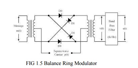
Ø Operation of Balance Ring Modulator:
Ring
modulation is a signal-processing function in electronics, an implementation of
amplitude modulation or frequency mixing, performed by multiplying two signals,
where one is typically a sine-wave or another simple waveform. It is referred
to as "ring" modulation because the analog circuit of diodes
originally used to implement this technique took the shape of a ring. This
circuit is similar to a bridge rectifier, except that instead of the diodes
facing "left" or "right", they go "clockwise" or
"anti-clockwise". A ring modulator is an effects unit working on this
principle.
The
carrier, which is AC, at a given time, makes one pair of diodes conduct, and
reverse-biases the other pair. The conducting pair carries the signal from the
left transformer secondary to the primary of the transformer at the right. If
the left carrier terminal is positive, the top and bottom diodes conduct. If
that terminal is negative, then the "side" diodes conduct, but create
a polarity inversion between the transformers. This action is much like that of
a DPDT switch wired for reversing connections.
Ring
modulators frequency mix or heterodyne two waveforms, and output the sum and
difference of the frequencies present in each waveform. This process of ring
modulation produces a signal rich in partials. As well, neither the carrier nor
the incoming signal is prominent in the outputs, and ideally, not at all.
Two
oscillators, whose frequencies were harmonically related and ring modulated
against each other, produce sounds that still adhere to the harmonic partials
of the notes, but contain a very different spectral make up. When the
oscillators' frequencies are not harmonically related, ring modulation creates
inharmonic, often producing bell-like or otherwise metallic sounds.
If
the same signal is sent to both inputs of a ring modulator, the resultant
harmonic spectrum is the original frequency domain doubled (if f1 =
f2 = f, then f2 − f1 = 0 and f2 + f1
= 2f). Regarded as multiplication, this operation amounts to
squaring. However, some distortion occurs due to the forward voltage drop of
the diodes.
Some
modern ring modulators are implemented using digital signal processing
techniques by simply multiplying the time domain signals, producing a
nearly-perfect signal output. Before digital music synthesizers became common,
at least some analog synthesizers (such as the ARP 2600) used analog
multipliers for this purpose; they were closely related to those used in
electronic analog computers. (The "ring modulator" in the ARP 2600
could multiply control voltages; it could work at DC.)
Multiplication
in the time domain is the same as convolution in the frequency domain, so the
output waveform contains the sum and difference of the input frequencies. Thus,
in the basic case where two sine waves of frequencies f1 and f2 (f1
< f2) are multiplied, two new sine waves are created, with one at
f1 + f2 and the other at f2 - f1. The two new waves are
unlikely to be harmonically related and (in a well designed ring modulator) the
original signals are not present. It is this that gives the ring modulator its
unique tones.
Inter
modulation products can be generated by carefully selecting and changing the
frequency of the two input waveforms. If the signals are processed digitally,
the frequency-domain convolution becomes circular convolution. If the signals
are wideband, this will cause aliasing distortion, so it is common to
oversample the operation or low-pass filter the signals prior to ring
modulation.
One
application is spectral inversion, typically of speech; a carrier frequency is
chosen to be above the highest speech frequencies (which are low-pass filtered
at, say, 3 kHz, for a carrier of perhaps 3.3 kHz), and the sum frequencies from
the modulator are removed by more low-pass filtering. The remaining difference
frequencies have an inverted spectrum - High frequencies become low, and vice
versa.
Ø Advantages:
Ø It allows
better management of the frequency spectrum. More transmission can fit into a
given frequency range than would be possible with double side band DSB signals.
All of
the transmitted power is message power none is dissipate as carrier power.
Ø Disadvantages:
1. The cost of a single side band SSB receiver is
higher than the double side band DSB counterpart be a ratio of about 3:1.
2. The
average radio user wants only to flip a power switch and dial a station. Single
side band SSB receivers require several precise frequency control settings to
minimize distortion and may require continual readjustment during the use of
the system.
Related Topics