Chapter: Communication Theory : Amplitude Modulation
Amplitude Modulation
AMPLITUDE MODULATION:
"Modulation is the process of superimposing
a low frequency signal on a high frequency carrier signal."
OR
"The process of modulation can be defined as
varying the RF carrier wave in accordance with the intelligence or information in a low frequency signal."
OR
"Modulation is defined as the precess by
which some characteristics, usually amplitude, frequency or phase, of a carrier is varied in accordance with
instantaneous value of some other voltage, called the modulating voltage."
ü Need For Modulation
1. If two
musical programs were played at the same time within distance, it would be
difficult for anyone to listen to one source and not hear the second source.
Since all musical sounds have approximately the same frequency range, form
about 50 Hz to 10KHz. If a desired program is shifted up to a band of
frequencies between 100KHz and 110KHz, and the second program shifted up to the
band between 120KHz and 130KHz, Then both programs gave still 10KHz bandwidth
and the listener can (by band selection) retrieve the program of his own
choice. The receiver would down shift only the selected band of frequencies to
a suitable range of 50Hz to 10KHz.
2. A
second more technical reason to shift the message signal to a higher frequency
is related to antenna size. It is to be noted that the antenna size is
inversely proportional to the frequency to be radiated. This is 75 meters at 1
MHz but at 15KHz it has increased to 5000 meters (or just over 16,000 feet) a
vertical antenna of this size is impossible.
3. The
third reason for modulating a high frequency carrier is that RF (radio
frequency) energy will travel a great distance than the same amount of energy
transmitted as sound power.
ü Types of Modulation
The
carrier signal is a sine wave at the carrier frequency. Below equation shows
that the sine wave has three characteristics that can be altered.
Instantaneous
voltage (E) =Ec(max)Sin(2πfct + θ)
The term
that may be varied are the carrier voltage Ec, the carrier frequency fc, and
the carrier phase angle θ. So
three forms of modulations are possible.
1.
Amplitude
Modulation
Amplitude
modulation is an increase or decrease of the carrier voltage (Ec), will all
other factors remaining constant.
2.
Frequency
Modulation
Frequency
modulation is a change in the carrier frequency (fc) with all other factors
remaining constant.
3.
Phase Modulation
Phase
modulation is a change in the carrier phase angle (θ). The phase angle cannot change
without also affecting a change in frequency. Therefore, phase modulation is in
reality a second form of frequency modulation.
ü EXPLAINATION
OF AM:
The
method of varying amplitude of a high frequency carrier wave in accordance with
the information to be transmitted, keeping the frequency and phase of the
carrier wave unchanged is called Amplitude Modulation. The information is
considered as the modulating signal and it is superimposed on the carrier wave
by applying both of them to the modulator. The detailed diagram showing the
amplitude modulation process is given below.
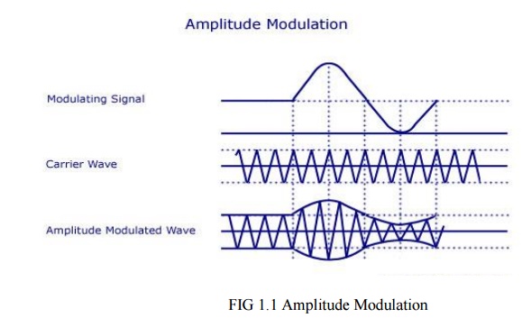
As shown
above, the carrier wave has positive and negative half cycles. Both these
cycles are varied according to the information to be sent. The carrier then
consists of sine waves whose amplitudes follow the amplitude variations of the
modulating wave. The carrier is kept in an envelope formed by the modulating
wave. From the figure, you can also see that the amplitude variation of the
high frequency carrier is at the signal frequency and the frequency of the
carrier wave is the same as the frequency of the resulting wave.
ü Analysis of Amplitude Modulation Carrier
Wave:
Let vc
= Vc Sin wct
vm
= Vm Sin wmt
vc
– Instantaneous value of the carrier
Vc
– Peak value of the carrier
Wc
– Angular velocity of the carrier
vm
– Instantaneous value of the modulating signal
Vm
– Maximum value of the modulating signal
wm
– Angular velocity of the modulating signal
fm
– Modulating signal frequency
It must
be noted that the phase angle remains constant in this process. Thus it can be
ignored.
The
amplitude of the carrier wave varies at fm.The amplitude modulated
wave is given by the equation A = Vc + vm = Vc
+ Vm Sin wmt
= Vc
[1+ (Vm/Vc Sin wmt)]
= Vc
(1 + mSin wmt)
m –
Modulation Index. The ratio of Vm/Vc.
Instantaneous
value of amplitude modulated wave is given by the equation v = A Sin wct
= Vc (1 + m Sin wmt) Sin wct
= Vc
Sin wct + mVc (Sin wmt Sin wct)
v = Vc
Sin wct + [mVc/2 Cos (wc-wm)t – mVc/2 Cos (wc + wm)t]
The above
equation represents the sum of three sine waves. One with amplitude of Vc and a
frequency of wc/2 , the second one with an amplitude of mVc/2
and frequency of (wc – wm)/2 and the third one with an
amplitude of mVc/2 and a frequency of (wc + wm)/2
.
In
practice the angular velocity of the carrier is known to be greater than the
angular velocity of the modulating signal (wc >> wm).
Thus, the second and third cosine equations are more close to the carrier
frequency. The equation is represented graphically as shown below.
ü Frequency
Spectrum of AM Wave:
Lower
side frequency – (wc – wm)/2
Upper
side frequency – (wc +wm)/2
The
frequency components present in the AM wave are represented by vertical lines
approximately located along the frequency axis. The height of each vertical
line is drawn in proportion to its amplitude. Since the angular velocity of the
carrier is greater than the angular velocity of the modulating signal, the
amplitude of side band frequencies can never exceed half of the carrier
amplitude.
Thus
there will not be any change in the original frequency, but the side band
frequencies (wc – wm)/2 and (wc +wm)/2
will be changed. The former is called the upper side band (USB) frequency and
the later is known as lower side band (LSB) frequency.
Since the
signal frequency wm/2 is present in the side bands, it is clear that
the carrier voltage component does not transmit any information.
Two side
banded frequencies will be produced when a carrier is amplitude modulated by a
single frequency. That is, an AM wave has a band width from (wc – wm)/2
to (wc +wm)/2 , that is, 2wm/2 or twice the
signal frequency is produced. When a modulating signal has more than one
frequency, two side band frequencies are produced by every frequency. Similarly
for two frequencies of the modulating signal 2 LSB‘s and 2 USB‘s frequencies
will be produced.
The side
bands of frequencies present above the carrier frequency will be same as the
ones present below. The side band frequencies present above the carrier
frequency is known to be the upper side band and all those below the carrier
frequency belong to the lower side band. The USB frequencies represent the some
of the individual modulating frequencies and the LSB frequencies represent the
difference between the modulating frequency and the carrier frequency. The
total bandwidth is represented in terms of the higher modulating frequency and
is equal to twice this frequency.
ü Modulation Index (m):
The ratio
between the amplitude change of carrier wave to the amplitude of the normal
carrier wave is called modulation index. It is represented by the letter ‗m‘.
It can
also be defined as the range in which the amplitude of the carrier wave is
varied by the modulating signal. m = Vm/Vc.
Percentage
modulation, %m = m*100 = Vm/Vc * 100
The
percentage modulation lies between 0 and 80%.
Another
way of expressing the modulation index is in terms of the maximum and minimum
values of the amplitude of the modulated carrier wave. This is shown in the
figure below.
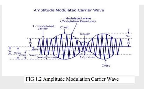
2 Vin =
Vmax – Vmin
Vin
= (Vmax – Vmin)/2
Vc = Vmax
– Vin
= Vmax
– (Vmax-Vmin)/2 =(Vmax + Vmin)/2
Substituting
the values of Vm and Vc in the equation m = Vm/Vc , we get
M = Vmax
– Vmin/Vmax + Vmin
As told
earlier, the value of ‗m‘ lies between 0 and 0.8. The value of m determines the
strength and the quality of the transmitted signal. In an AM wave, the signal
is contained in the variations of the carrier amplitude. The audio signal
transmitted will be weak if the carrier wave is only modulated to a very small
degree. But if the value of m exceeds unity, the transmitter output produces
erroneous distortion.
ü Power Relations in an AM wave:
A
modulated wave has more power than had by the carrier wave before modulating.
The total power components in amplitude modulation can be written as:
Ptotal =
Pcarrier + PLSB + PUSB
Considering
additional resistance like antenna resistance R.
Pcarrier
= [(Vc/√2)/R]2
= V2C/2R
Each side
band has a value of m/2 Vc and r.m.s value of mVc/2√2. Hence power in LSB and USB can
be written as
PLSB
= PUSB = (mVc/2√2)2/R
= m2/4*V2C/2R = m2/4 Pcarrier
Ptotal
= V2C/2R + [m2/4*V2C/2R] + [m2/4*V2C/2R]
= V2C/2R (1 + m2/2) = Pcarrier (1 +
m2/2)
In some
applications, the carrier is simultaneously modulated by several sinusoidal
modulating signals. In such a case, the total modulation index is given as
Mt = √(m12 + m22
+ m32 + m42 + …..
If Ic and
It are the r.m.s values of unmodulated current and total modulated current and
R is the resistance through which these current flow, then
Ptotal/Pcarrier
= (It.R/Ic.R)2 = (It/Ic)2
Ptotal/Pcarrier
= (1 + m2/2)
It/Ic = 1
+ m2/2
ü Limitations of Amplitude Modulation:
1. Low
Efficiency- Since the useful power that lies in the small bands is quite small,
so the efficiency of AM system is low.
2. Limited
Operating Range – The range of operation is small due to low efficiency. Thus,
transmission of signals is difficult.
3. Noise in
Reception – As the radio receiver finds it difficult to distinguish between the
amplitude variations that represent noise and those with the signals, heavy
noise is prone to occur in its reception.
4. Poor
Audio Quality – To obtain high fidelity reception, all audio frequencies till
15 KiloHertz must be reproduced and this necessitates the bandwidth of 10
KiloHertz to minimise the interference from the adjacent broadcasting stations.
Therefore in AM broadcasting stations audio quality is known to be poor.
Related Topics