Chapter: Electronic Circuits : Tuned Amplifiers
Resonance circuits
Resonance circuits
The frequency applied to an LCR circuit causes
XL and XC to be equal, and the circuit is RESONANT. If XL and XC are equal ONLY
at one frequency (the resonant frequency). This fact is the principle that
enables tuned circuits in the radio receiver to select one particular frequency
and reject all others.
This is the reason why so much emphasis is
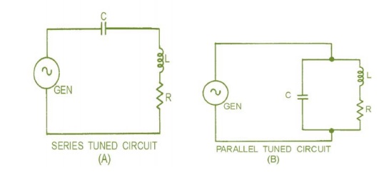
placed on XL and X C . figure 1-1 Shows that a basic tuned circuit consists of
a coil and a capacitor, connected either in series, view (A), or in parallel,
view (B). The resistance (R) in the circuit is usually limited to the inherent
resistance of the components (particularly the resistance of the coil).

Tuned
amplifier
ü Communication circuit widely uses tuned
amplifier and they are used in MW & SW radio frequency 550 KHz – 16 MHz, 54
– 88 MHz, FM 88 – 108 MHz, cell phones 470 - 990 MHz
ü Band width is 3 dB frequency interval of pass
band and –30 dB frequency interval
ü Tune amplifiers are also classified as A, B, C
similar to power amplifiers based on conduction angle of devices.
Series
resonant circuit
Series resonant features minimum impedance (RS)
at resonant.
ü f r = ½ √LC; q = L/Rs at resonance L=1/c,
BW=fr/Q
ü It behaves as purely resistance at resonance,
capacitive below and inductive above resonance
Paralel
resonant circuit
ü Paralel resonance features maximum impedance at
resonance = L/RsC
ü At resonance Fr=1/2√1/(LC-Rs2/L2); if Rs=0,
fr=1/2√(LC)
ü At resonance it exhibits pure resistance
and below fr parallel circuit exhibits
inductive and above capacitive impedance
Related Topics