Chapter: Protection and Switchgear : Theory of Circuit Interruption
Resistance switching
Resistance switching
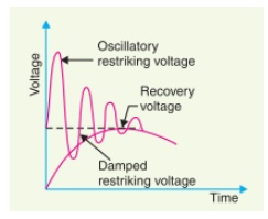
To reduce the restriking voltage, RRRV and severity of the transient oscillations, a resistance is connected across the contacts of the circuit breaker.
This is known as resistance switching. The resistance is in parallel with the arc. A part of the arc current flows through this resistance resulting in a decrease in the arc current and increase in the deionization of the arc path and resistance of the arc.
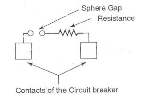
This process continues and the current through the shunt resistance increases and arc current decreases. Due to the decrease in the arc current, restriking voltage and RRRV are reduced. The resistance may be automatically switched in with the help of a sphere gap as shown in Fig. The resistance switching is of great help in switching out capacitive current or low inductive current.
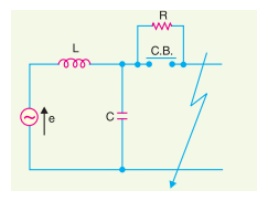
The analysis of resistance switching can be made to find out the critical value of the shunt resistance to obtain complete damping of transient oscillations. Figure 5.8 shows the equivalent electrical circuit for such an analysis.
Unipolar switching
Unipolar systems usually have a dielectric that is a simple TMO. Examples are NiO [12], CuO, CoO, Fe2O3 , HfO, TiO2Ta2O5 , Nb2O5 [10,11]. These systems are good insulators with a large resistivity. They would normally not show any RS effect. To get the systems into the switching regime it is usually required to perform and initial ‗electroforming‘ step. In this process, a strong electric field is applied, which brings the system close to the dielectric break down. A full break down is prevented by a current limitation or compliance. After this ‗SET‘ procedure, the resistance of the device shows a significant decrease, reaching a ‗low resistance‘ state, RLO , which is stable, i.e., non-volatile. This state has an ohmic I-V characteristic at low bias. To switch the system to the ‗high resistance‘ state, RHI ,a voltage has to be applied to the device, with either the same or opposite polarity than the previously applied ‗forming‘ voltage. In this ‗RESET‘ step, the resistance of the system suddenly increases, back to a ‗high resistance‘ value close to the original one.
No current compliance should be used in the RESET step. In fact, the resistance change occurs when the current through the device becomes larger than the value of the compliance. To SET the system again in the low resistance state, a voltage with current compliance has to be once again applied, similarly to the forming step. The system‘s resistance suddenly decreases down to a value close to RLO at a threshold voltage Vth , which is smaller that the forming one. The SET and RESET switching process can be repeated may times. The magnitude of resistance change typically remains within well-defined values, however some dispersion is often observed. An example of a typical electroforming and successive RESET and SET steps are shown in Fig
Bipolar switching
Bipolar resistive switching has been observed in a variety of ternary oxides with perovskite structure such as SrTiO3(STO), SrZrO3 , and also in more complex systems such as the ‗colossal‘ magnetoresistive manganites LSMO, LCMO, PCMO, PLCMO, and even in cuprate superconductors YBCO and BSCCO. Some reports indicate that better performance may be obtained by small chemical substitution, such as Bi:SrTiO3 and Cr:SrTiO3 . These bipolar systems may be either insulators or poor metals. Strong hysteresis in the two-terminal resistance is often observed without the need of an initial forming step. Nevertheless, electro-forming usually done, as it may improve the reproducibility of resistive switching, but this initial forming step remains not well understood .
The choice of a proper electrode material for each dielectric is an important issue for bipolar devices. Sawa and collaborators have performed a systematic study, concluding that a key feature for RS is the formation of Shottky barriers [10]. In fact, the observed scaling of RHI and RLO with the geometry of the devices indicate that the phenomenon should take place at the electrode/oxide interfaces.
Related Topics