Chapter: Fundamentals of Database Systems : Conceptual Modeling and Database Design : Practical Database Design Methodology and Use of UML Diagrams
Rational Rose: A UML-Based Design Tool
Rational Rose: A UML-Based Design Tool
1. Rational Rose for
Database Design
Rational Rose is one of the modeling tools used in the industry to
develop information systems. It was acquired by IBM in 2003. As we pointed out
in the first two sections of this chapter, a database is a central component
of most information systems. Rational Rose provides the initial specification
in UML that eventually leads to the database development. Many extensions have
been made in the latest versions of Rose for data modeling, and now it provides
support for conceptual, logical, and physical database modeling and design.
2. Rational Rose Data
Modeler
Rational Rose Data Modeler is a visual modeling tool for designing
databases. Because it is UML-based, it provides a common tool and language to
bridge the communication gap between database designers and application
developers. This makes it possible for database designers, developers, and
analysts to work together, capture and share business requirements, and track
them as they change through-out the process. Also, by allowing the designers to
model and design all specifications on the same platform using the same
notation, it improves the design process and reduces the risk of errors.
The process modeling capabilities in Rational Rose allow the modeling of
the behavior of database applications as we saw in the short example above, in
the form of use cases (Figure 10.8), sequence diagrams (Figure 10.12), and
statechart diagrams (Figure 10.11). There is the additional machinery of
collaboration diagrams to show interactions between objects and activity
diagrams to model the flow of control, which we did not show in our example.
The eventual goal is to generate the database specification and application
code as much as possible. The Rose Data Modeler can also capture triggers,
stored procedures, and other modeling concepts explicitly in the diagram rather
than representing them with hidden tagged values behind the scenes (see Chapter
26 which discusses active databases and triggers). The Rose Data Modeler also
provides the capability to forward
engineer a database in terms of constantly changing requirements and reverse engineer an existing implemented
database into its conceptual design.
3. Data Modeling Using
Rational Rose Data Modeler
There are many tools and options available in Rose Data Modeler for data
modeling.
Reverse Engineering. Reverse engineering of a database allows the user to create a conceptual data model based on an existing database schema specified
in a DDL file. We can use the reverse engineering wizard in Rational Rose Data
Modeler for this purpose. The reverse engineering wizard basically reads the
schema in the data-base or DDL file and recreates it as a data model. While
doing so, it also includes the names of all quoted identifier entities.
Forward Engineering and DDL
Generation. We can also create a data model directly from scratch in Rose. Having created the data model, we can
also use it to generate the DDL for a specific DBMS. There is a forward
engineering wizard in the Rose Data Modeler that reads the schema in the data
model or reads both the schema in the data model and the tablespaces in the
data storage model and generates the appropriate DDL code in a DDL file. The
wizard also provides the option of generating a database by executing the
generated DDL file.
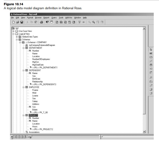
Conceptual Design in UML
Notation. Rational Rose allows modeling of
data-bases using UML notation. ER diagrams most often used in the conceptual
design of databases can be easily built using the UML notation as class
diagrams in Rational Rose. For example, the ER schema of our COMPANY database
from Chapter 7 can be redrawn in Rose using UML notation as shown in Figure
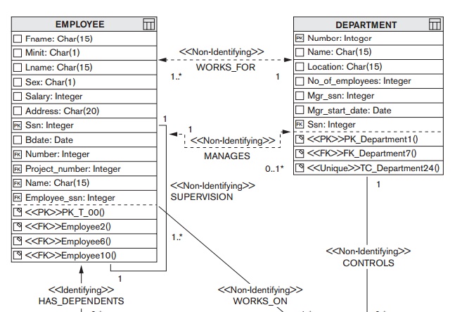
10.14. The textual specification in Figure 10.14 can be converted to the
graphical representation shown in Figure 10.15 by using the data model diagram
option in Rose.
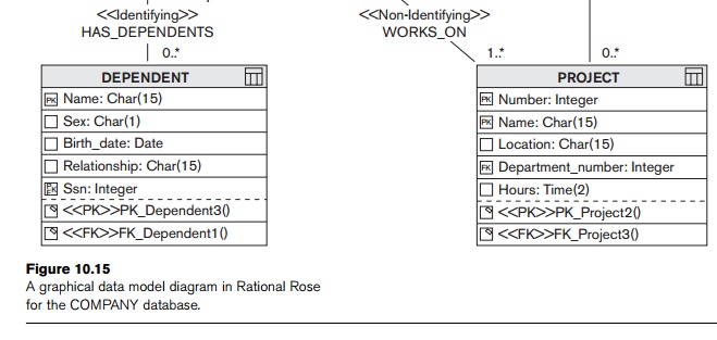
Figure 10.15 is similar to Figure 7.16, except that it is using the
notation provided by Rational Rose. Hence, it can be considered as an ER
diagram using UML notation, with the inclusion of methods and other details. Identifying relationships specify that
an object in a child class (DEPENDENT in Figure 10.15) cannot exist
without a corresponding parent object in the parent class (EMPLOYEE in Figure 10.15),
whereas non-identifying
relationships specify a regular association (relationship) between two
independent classes. It is possible to update the schemas directly in their
text or graphical form. For example, if the relationship between the EMPLOYEE and
PROJECT called WORKS_ON was deleted, Rose would automatically update or delete all the foreign
keys in the relevant tables.
An important difference in Figure 10.15 from our previous ER notation
shown in Chapters 7 and 8 is that foreign key attributes actually appear in the
class diagrams in Rational Rose. This is common in several diagrammatic
notations to make the conceptual design closer to the way it is realized in the
relational model implementation. In Chapters 7 and 8, the conceptual ER and
EER diagrams and the UML class diagrams did not include foreign key attributes,
which were added to the relational schema during the mapping process (see
Chapter 9).
Converting Logical Data
Model to Object Model and Vice Versa. Rational Rose Data Modeler also provides the option of converting a logical
database design (relational schema) to an object model design (object schema)
and vice versa. For example, the logical data model shown in Figure 10.14 can
be converted to an object model. This sort of mapping allows a deep
understanding of the relationships between the conceptual model and
implementation model, and helps in keeping them both up-to-date when changes
are made to either model during the develop-ment process. Figure 10.16 shows
the Employee table after converting it to a class in an object model. The
various tabs in the window can then be used to enter/display different types of
information. They include operations, attributes, and relation-ships for that
class.
Synchronization between the
Conceptual Design and the Actual Database. Rose Data
Modeler allows keeping the data model and database imple-mentation
synchronized. It allows visualizing both the data model and the database and
then, based on the differences, it gives the option to update the model or
change the database.
Extensive Domain Support. The Rose Data Modeler allows database designers to create a standard set of user-defined data types (these are similar
to domains in
SQL; see Chapter 4) and assign them to any column in the data model.
Properties of the domain are then cascaded to assigned columns. These domains
can then be maintained by a standards group and deployed to all modelers when
they begin creating new models by using the Rational Rose framework.
Easy Communication among
Design Teams. As mentioned earlier, using a common tool allows easy communication between teams. In the Rose Data
Modeler, an application developer can access both the object and data models
and see how they are related, and thus make informed and better choices about
how to build data access methods. There is also the option of using Rational Rose Web Publisher to allow the models and the meta-data beneath these
models to be avail-able to everyone on the team.
What we have described above is a partial description of the
capabilities of the Rational Rose tool as it relates to the conceptual and
logical design phases in Figure 10.1. The entire range of UML diagrams we
described in Section 10.3 can be developed and maintained in Rose. For further
details the reader is referred to the product literature. Figure 10.17 gives
another version of the class diagram in Figure 7.16 drawn using Rational Rose.
Figure 10.17 differs from Figure 10.15 in that the foreign key attributes are
not shown explicitly. Hence, Figure 10.17 is using the notations presented in
Chapters 7 and 8. Rational Rose allows either option to be used, depending on
the preference of the designers.
Related Topics