Chapter: Environmental Engineering : Collection and conveyence of water
Pumps And Pumping Stations

PUMPS AND PUMPING STATIONS
PURPOSE
I.
To
lift the water from source to the treatment plant which is at higher level
compared to the source
II.
To
lift the treated water to the elevated tanks
III.
To
increase the pressure in the distribution system.
IV. To lift the water at the treatment plant if
sufficient natural ground slope is not available as to cause gravitational flow
between different units of treatment plants.
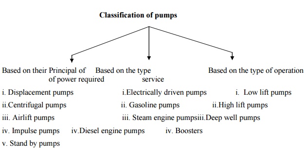
Classification of Pumps
Based
on their Principal of power required
i.
Displacement pumps
ii.Centrifugal
pumps
iii.
Airlift pumps
iv.
Impulse pumpsiv.Diesel engine pumps
v.
Stand by pumps
Based
on the type service
i.Electrically
driven pumps
ii.
Gasoline pumps
iii.
Steam engine pumps
iv.
Boosters
Based
on the type of operation
i. Low lift pumps
ii.High
lift pumps
iii.Deep
well pumps
Under most of the situations in
water supply scheme, displacement and centrifugal pumps are commonly used.
Displacement pumps
i.
Reciprocating
pumps
ii.
Rotary
pumps
PUMPING STATIONS
The
location of a pumping station is primarily governed by the place where it is to
recerive water. The points to be kept in mind while selecting a suitable site
are.
i.
The
site should be away from all the sources of contamination or pollution
ii.
The
site should be above the HFL of the river.
iii.
Its
future growth and expansion is easily possible
iv.
Possibility
of fire hazards is also to be considered
FACTORS AFFECTING THE SELECTION OF A PARTICULAR TYPE OF PUMP
1. Capacity of pumps
2. Importance of WSS
3. Initial cost of pumping arrangement
4. Maintenance cost
5. Space requirements for locating the
pumps
6. Number of units required
7. Total life of water required
8. Quantity of water to be pumped.
HEAD POWER AND EFFICIENCY OF PUMPS
The total head against which a pump
works is made up of
i.
The
suction Head(Hs)
ii.
The
Delivery Head(Hd)
iii.
The
Head loss due to friction entrance and exit in the rising main(Hf)
The suction HEAD is the difference
in elevation between the low water level and center line of pump.
Delivery HEAD is the difference in
elevation between the pump center line and point of discharge
Total HEAD (H) =Hs+Hd+Hf
The
work done by the pump in lifting „Q? cumecs of water by a head(H) =WQH kg-m/sec.
Where,
W = Specific weight of water, 1000
kg/m3 Q = discharge to be pumped, m3/sec.
The water horse power of the pump is
given by
WHP(out put) = WQH/75
If „n? is the efficiency of the pump
then
BRAKE HORSE POWER of the pump is given by
BHP(INPUT) + WQH/75n
ECONOMICAL DIAMETER OF THE RISING (PUMPING) MAIN
The
economical diameter is a particular size of the pumping or rising main which
while passing a given discharge of water gives the total annual expense to be
minimum.
If the diameter chosen is more than
the economic dia, it will lead to higher cost of the pipe line on the other
hand, if the dia of the pipe is less than the economical dia, the increased
velocity will lead to higher friction headless and require more HP for the
required pumping and the cost of pumping shall be much more than the resultant
saving in the pipe cost.
LEA FORMULA
An empirical formula given by LEA
Connecting the dia and discharge is
given by
D
= 0.97 to 1.22 ![]() SqRt(Q)
SqRt(Q)
Where
D = economical diain m
Q = Discharge to be pumped in cusecs
This relation gives optimum flow
velocity varying between 0.8 to 1.35m/sec
FOR
RIGOROUS ANALYSIS The
total cost of pipe and pumping should be woeked out at different assumed velocities (b/w 0.8 to 1.8m/sec) and a graph
plotted between the annual cost and the size of the pipe. The economical size
is one which gives the least annual cost.
Related Topics