Chapter: Fiber optics and Laser instruments : Optical Fiber and Their Properties
Principle of light propagation through a fibre
Principle of light propagation
through a fibre
a.
Total internal reflection
b.
Acceptance angle (θa)
c.
Numerical aperture.
d.
Skew mode.
1. Total internal reflection.
i) Index of refraction:
This is
the measuring speed of light in respective medium. It is calculated by dividing
speed of light in vacuum to the speed of light in material. The RI for vacuum
is 1, for the cladding material of optical fiber it is 1.46, the core value of
RI is 1.48(core RI must be more than cladding material RI for transmission. it
means signal will travel around 200 million meters per second. it will 12000 km
in only 60 seconds, other delay in communication will be due to communication
equipment switching and decoding, encoding the voice of the fiber.
ii) Snell’s law :
In order
to understand ray propagation in a fiber. This is called Snell’s Law.
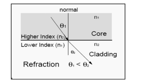
n1
sin .01 = n2 sin .02
Where n
denotes the refractive index of material. 01/02 is angles
in respective medium. Higher refractive index means denser medium.
1
When light enters in lighter medium from denser
medium it inclines towards normal.
2
When light enters in denser medium from lighter
medium it inclines to normal.
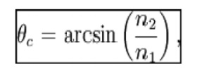
Critical Angle –
If we
consider we notice above that as angle 01 becomes larger and larger so does
angle 02. Because of the refraction effect 02 becomes large more quickly than
01. At the same point
02 will
reach 90° while 01 is still well less than that. This is called “critical
angle”. When
01
increase further then refraction ceases and the light starts to be reflected
rather than refracted. Thus light is perfectly reflected at an interface
between two materials of different refractive index if:
Total Internal Reflection (TIR) –
When
light traveling in a dense medium hits a boundary at a steep angle (larger than
the "critical angle “for the boundary), the light will be completely
reflected. This phenomenon is called total
internal reflection. This effect is
used in optical fibers to confine light in the core. Light travels along the fiber bouncing back and
forth off of the boundary; because the light must strike the boundary with an
angle greater than the critical angle, possible in air to glass. If we now
consider above Figures we can see the effect of the critical only light that
enters the fiber certain range of angles can travel down the fiber without
leaking out. Total internal reflection occurs when light enters from higher
refractive index to lower refractive index material, i.e. from glass to air
total internal reflection is possible but it is not possible in air to glass.
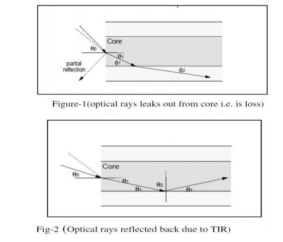
we see
that for rays where angle 01 less than a critical value then the ray will
propagate along the fiber and will be bound within the fiber. In fig. 1 we see
that where the angle 01 is greater than critical value the ray is refracted
into the cladding and will ultimately be lost outside the fiber. This is loss.
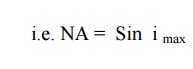
2. Acceptance angle (θa)
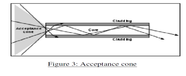
The
maximum incident angle below which the ray undergoes the total internal
reflection is called an acceptance angle. The cone is referred as acceptance
cone.When we consider rays entering the fiber from the outside (into the end
face of fiber) we see that there is a further complication. The refractive
index difference between the fiber core and the air will cause any arriving ray
to be refracted. This means that there is a maximum angle for a ray arriving at
the fiber end face at which the ray will propagate. Rays arriving at an angle
less than this angle will propagate but rays arriving at greater angle will
not. This angle is not a “critical angle” as that term is reserved for the case
where light arrives from a material of higher RI to one of lower RI (In this,
case the critical angle is the angle within the fiber). Thus there is
“cone of
acceptance” at the endface of a fiber. Rays arriving within the cone will
propagate and ones arriving outside of it will not. The acceptance cone is
function of difference of RI of core and cladding
3. Numerical aperture (NA)
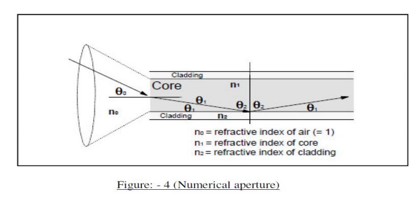
It is defined as the sine of acceptance angle of the fiber.
One of the most often quoted characteristics of an optical fiber is its “Numerical Aperture”. The NA is intended as a measure of the light capturing ability of the fiber. However it is used for many other purposes. For example it may be used as a measure of the amount of loss that we might expect on a bend of a particular radius etc.This ray will be refracted and will later encounter the core-cladding interface at an angle such that it will be reflected. This is because the angle 02 is greater than the critical angle. The angle is greater because we are measuring angle from a normal to the core-cladding boundary not a tangent to it.
This one
will reach the core- cladding interface at an angle smaller than the critical
angle it will pass into the cladding. This ray will eventually be lost. It is
clear that there is a “cone” of acceptance If ray enters the fiber at an angle
within the cone then it will be captured and propagatesas a bound mode. If a
ray enters the fiber at an angle outside the cone then it will leave the core
and eventually leave the fiber itself.The Numerical Aperture is the sign of
the largest angle contained within the cone of acceptance.
An expression for an Acceptance angle and Numerical
aperture
Let us
consider an optical fiber, where n0=Refractive Index of Air; n1
= Refractive Index of Core; n2 = Refractive Index of Cladding.
The ray
AO enter from air into core at an incident angle ‘i’ Refract thro OBat an angle
‘q’
Finally,
it is incident from core to cladding surface at an angle фC.A
At the
incident angle is critical angle (фC), the ray just moves along
interface BC.
Hence, the angle of incidence (фC = 90 – q) at the interface of core and cladding will be more than the critical angle. Hence the ray is totally internally reflected ray.
Thus, only those ray which passes within the acceptance angle will be totally internally reflected. Therefore, the light incident on the core within this maximum external incident angle can be coupled into the fiber to propagate. This angle is called as an acceptance angle.
4. Skew mode
The rays
follows a helical path through the fiber is called skew ray. The light
traveling down the fiber is a group of electromagnetic (EM) waves occupying a
small band of frequencies within the electromagnetic spectrum, so it is a
simplification to call it a ray of light. However, it is enormously helpful to
do this, providing an easy concept, some framework to hang our ideas on. We do
this all the time and it serves us well providing we are clear that it is only
an analogy. Magnetic fields are not really lines floating in space around a
magnet, electrons are not really little black ball bearings flying round a red
nucleus. Light therefore, is propagated as an electromagnetic wave along the
fiber. The two components, the electric field and the magnetic field form
patterns across the fiber. These patterns are called modes of transmission.
Modes
means methods — hence methods of transmission. An optic fiber that carries more
than one mode is called a multimode fiber (MM). The number of modes is always a
whole number. In a given piece of fiber, there are only a set number of
possible modes. This is because each mode is a pattern of electric and magnetic
fields having a physical size. The dimensions of the core determine how many
modes or patterns can exist in the core — the larger the core, the more modes.
The number of modes is always an integer, we cannot have incomplete field
patterns. This is similar to transmission of motor vehicles along a road. As
the road is made wider, it stays as a single lane road until it is large enough
to accommodate an extra line of vehicles whereupon it suddenly jumps to a two
lane road. We never come across a 1.15 lane road!
Related Topics