Chapter: Mechanical : Finite Element Analysis : One Dimensional Finite Element Analysis
One Dimensional Finite Element Analysis
ONE DIMENSIONAL FINITE ELEMENT ANALYSIS
ONE
DIMENSIONAL ELEMENTS
Bar and beam elements are considered as One
Dimensional elements. These elements are often used to model trusses and frame
structures.
Ø Bar, Beam and Truss
Bar is a member which resists only axial loads. A
beam can resist axial, lateral and twisting loads. A truss is an assemblage of
bars with pin joints and a frame is an assemblage of beam elements.
Ø Stress, Strain and Displacement
Stress is denoted in the form of vector by the
variablexasσx, Strain
is denoted in the form of vector by the variable x as ex,
Displacement is denoted in the form of vector by the variable x as ux.
Ø Types of
Loading
(1) Body force (f)
It is a distributed force acting on every
elemental volume of the body. Unit is Force / Unit volume. Ex: Self weight due
to gravity.
(2)
Traction (T)
It is a distributed force acting on the surface of
the body. Unit is Force / Unit area. But for one dimensional problem, unit is
Force / Unit length. Ex: Frictional resistance, viscous drag and Surface shear.
(3) Point
load (P)
It is a
force acting at a particular point which causes displacement.
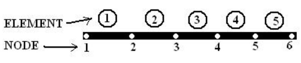
Ø Finite Element Modeling
It has
two processes.
(1) Discretization
of structure
(2) Numbering
of nodes.
Ø CO –
ORDINATES
(A) Global co –ordinates,
(B) Local co –ordinates and
(C) Natural co –ordinates.
Ø Natural
Co – Ordinate (ε)
Integration
of polynomial terms in natural co –ordinates
for two dimensional elements can be performed by using the formula,
Shape function
N1N2N3 are usually denoted as shape function. In one
dimensional
problem,
the displacement
u = SNi ui =N1 u1
For two
noded bar element, the displacement at any point within the
element
is given by,
u = SNi ui =N1 u1 + N2
u2
For three
noded triangular element,
the displacement at any point
within
the element is given by,
u = SNi ui =N1 u1 + N2
u2 + N3 u3
v = SNi vi =N1 v1 + N2
v2 + N3 v3
Shape
function need to satisfy the following
(a) First
derivatives should be finite within an element; (b) Displacement should
be
continuous across the element boundary
Polynomial Shape function
Polynomials
are used as shape function due to the following reasons, (1)
Differentiation
and integration of polynomials are quite easy.
(2) It is
easy to formulate and computerize the finite element equations.
(3) The
accuracy of the results can be improved by increasing the order of
Ø Properties
of Stiffness Matrix
1. It is a
symmetric matrix,
2. The sum
of elements in any column must be equal to zero,
3. It is an
unstable element. So the determinant is equal to zero.
Ø Problem
(I set)
1.A two
noded truss element is shown in figure. The nodal displacements are u1
= 5 mm and u2 = 8 mm. Calculate the displacement at x = ¼ , 1/3 and
½ .
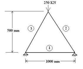
Ø Problem
(II set)
1. Consider
a three bar truss as shown in figure. It is given that E = 2 x 10⁵
N/mm2. Calculate
(a) Nodal displacement,
(b) Stress in
each member and
(c) Reactions
at the support. Take Area of element 1 = 2000 mm2, Area of element 2
= 2500 mm2, Area of element 3 = 2500 mm2.
Ø Types of
beam
1. Cantilever
beam,
2. Simply
Supported beam,
3. Over
hanging beam,
4. Fixed
beam and
5. Continuous
beam.
Ø Types of
Transverse Load
1. Point or
Concentrated Load,
2. Uniformly
Distributed Load and
3. Uniformly
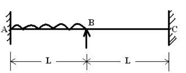
Ø Problem
(III set)
1. A fixed beam of length 2L m carries a uniformly distributed
load of w (N/m)
which
runs over a lengt h of L m from the fixed end. Calculate the rota tion at Point
B.
LINEAR
STATIC ANALYSIS( BAR ELEMENT)
Most structural analysis pro
blems can be treated as linear static problems, b ased on the following
assumptions
1.Small
deformations (loading pattern is not changed due to the defor med shape)
2.Elastic
materials (no plasticity or failures)
3.Static
loads (the load is applied to the structure in a slow or steady fashion)
Linear analysis can pro vide most of the information
about the behavior of a structure, and can be a good ap proximation for many
analyses. It is also the ba ses of nonlinear analysis in most of th e cases.
BEAM ELEMENT
A beam element is defin ed as a
long, slender member (one dimension i s much larger than the other two) that is
subje cted to vertical loads and moments, which pro duce vertical displacements
and rotations. T he degrees of freedom for a beam element are a vertical
displacement and a rotation at e ach node, as opposed to only an horizontal di
splacement at each node for a truss element.
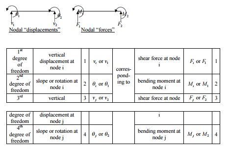
Degrees of Freedom
Degrees of freedom are defined as
the number of independent coordina tes necessary to specify the configuration
of a system. The degrees of freedom for a general situation consists of three
translations in t he x, y, and z directions and three rotations
abou t the x, y, and z axes. A one-dimensional beam element has
four degrees of freedom, which include, a vertical displacement and a
rot ation at each node.

Assumptions
Nodal Forces and Moments
Forces and moments can only be
applied at the nodes of the beam element, not between the nodes. The nodal
forces and moments, fc, are related to the nodal displacements and rotations, ![]()
![]() through the ele ment stiffness
matrix,Kv.
through the ele ment stiffness
matrix,Kv.
Constant Load
The loads that are appli ed to
the beam element are assumed to be stat ic and not to vary over the time period
being considered, this assumption is only valid if the r ate of change of the
force is much less than th e applied force (F >> dF/dt). If
the loads vary significantly, (if the variation in load is not much less than
the applied force) then the pro blem must be considered as dynamic.
Weightless Member
The weight (W) of the beam is
neglected, if it is much less than the total resultant forces (F) acting on the
beam. If the weight of the beam is not neglected, then its effects must be
represented as vertical forces acting at the nodes, by dividing up the weight
and lumping it at the nodes, proportionally according to it's placement along
the beam.
Prismatic Member
The beam element is assumed to
have a constant cross-section, which m eans that the cross-sectional area and
the mom ent of inertia will both be constant (i.e., the be am element is a
prismatic member). If a bea m is stepped, then it must be divided up into
sections of constant cross-section, in order to obtain an exact solution. If a
beam is tape red, then the beam can be approximated by us ing many small beam
elements, each having the same cross-section as the middle of the tap ered
length it is approximating. The more sections that are used to approximate a
tapered be am, the more accurate the solution will be.
The moment of inertia is a geometric
property of a beam element, which describes the beams resistance to bending and
is assumed to be constant through the length of the element. The moment of
inertia can be different along different axes if the beam el ement is not
symmetric, we use the moment of inertia (I) of the axis about which the bendin
g of the beam occurs
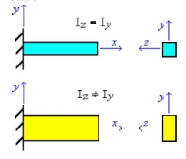
Where (Iz)
refers to the moment of inertia, resisting bending about the "z"
axis and (Iy) about the "y" axis.
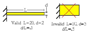
The Beam Element is a Slende r Member
A beam is assumed to be a slender
member, when it's length (L) is moree than 5 times as long as either of it's
cross-sec tional dimensions (d) resulting in (d/L<.2). A beam must be
slender, in order for the beam equations to apply, that were used to derive our
FEM equations.
The Beam Bends without Twisting.
It is assumed that the c
ross-section of the beam is symmetric about the plane of bending (x-y
plane in this case) and will undergo symmetric bending (where n o twisting of
the beam occurs during the bend ing process). If the beam is not symmetric abo
ut this plane, then the beam will twist during bending and the situation will
no longer be on e-dimensional and must be approached as an u nsymmetric bending
problem (where the beam twists while bending) in order to obtain a cor rect
solution.
Cross Section Remains Plane
When a beam element b ends, it is
assumed that it will deflect uniformly, thus the cross section will move
uniform ly and remain plane to the beam centerline. In other words, plane
sections remain plane and normal to the x axis before and after bending.
Axially Rigid
The one-dimensional bea m element
is assumed to be axially rigid, mean ing that there will be no axial displacement
( u) along the beams centriodal axis. This implies that forces will only
be applied perpendicular to the beams centriodal axis. The one-dimensional beam
element can be used only when the degrees of freedom are limited to vertical
displacements (perpendicular to the beams centriodal axis) and rotations in one
plane. If axial displacements are present then a one-dimen sional bar element
must be superimposed w ith the one-dimensional beam element in ordder to obtain
a valid solution.
Homogenous Material
A beam element has the s ame
material composition throughout and there fore the same mechanical properties
at every position in the material. Therefore, the modulus of elasticity E is
constant throughout the beam element. A member in which the material properties
varies from one point to the next in t he member is called inhomogenous
(non-homo genous). If a beam is composed of different ty pes of materials, then
it must be divide up into elements that are each of a single homogeneous
material, otherwise the solution will not be exact.
Isotropic Material
A beam element has the same
mechanical and physical properties in all directions, i.e., they are
independent of dir ection. For instance, cutting out three tensile test
specimens, one in the x-direction, one in t he y-direction and
the other oriented 45 degre es in the x-y plane, a tension test
on each s pecimen, will result in the same value for th e modulus of elasticity
(E), yield strength and ultimate
strength. Most metals arre considered isotropic. In contrast fibrous m
aterials, such as wood, typically have properties that are directionaly
dependant and are generally considered anisotropic (not isotropic).
The Proportional Limit is not Exceeded
It is assumed that the b eam
element is initially straight and unstressed. It is also assumed that the
material does n ot yield, therefore the beam will be straight af ter the load
is released. These assumptions me an that the beam must be made of an elastic
material, one which will return to it's original size and shape when all loads
are removed, if not stressed past the materials elastic or proportional limit.
It is also assumed that the beam is not stressed past the proportional limit,
at w hich point the beam will take a permanent set and will not fully return to
it's original size an d shape, when all loads are removed. Below th e
proportional limit an elastic material is in the linear elastic range, where
the strain varies linearly with the
applied load and the stress ( ) varies
linearly according to: σ = Eε , where E is the modulus
of elasticity.
Rigid Body Modes for the
One-Dimensional Beam Element
Rigid Body Modes for the
One-Dimensional Beam Element
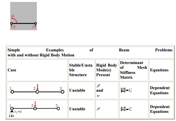
Rigid body motion occurs when
forces and/or moments are applied to an unrestrained mesh (body), resulting in
motion that occurs without any deformations in th e entire mesh (body). Since
no strains (deformations) occur during rigid body motion, there can be no
stresses developed in the mesh. In order to obtain a unique FEM solution, rigid
body motion must be constrained. If rigid body motion is not constrained, then
a singular system of equations will result, since the determinate of the mesh
stiffness matrix is equal to zero (i.e., ( |K| - 0)
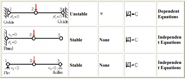
There are two rigid body modes for
the one-dimensional beam element , a translation (displacement) only and a
rotation only. These two rigid body modes can occu r at the same time resulting
in a displacement and a rotation simultaneously. In order to e liminate rigid
body motion in a 1-D beam elem ent (body), one must prescribe at least two no
dal degrees of freedom (DOF), either two displacements or a
displacement and a rotation. A DOF can be equal to zero or a non-zero know n
value, as long as the element is restrained fro m rigid body motion
(deformation can take pl ace when forces and moments are applied) .
For simplicity we will in troduce
the rigid body modes using a mesh c omposed of a single element. If only translatio
nal rigid body motion occurs, then the displaceement at local node I
will be equal to the displacement at local node J. Since the displacem
ents are equal there is no strain developed in t he element and the applied
nodal forces cause the element to move in a rigid (non-deflected) vertical
motion (which can be either up as show n below or it can be in the downward
directio n depending on the direction of the applied force s).
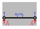
This
rigid body mode can be suppressed by prescribing a vertical nodal displace
ment.
If rotational rigid body motion
occurs, then the rotation at local node I will be equal to the rotation
at local node J (i.e., in magnitude and direction). In this situation th
e nodal forces and/or moments applied to the element, cause the element to
rotate as a rigid body (either clockwise as shown below or counterclockwise
depending on the direction o f the applied forces and/or moments).
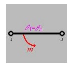
This
rigid body mode can be suppressed by prescribing a nodal translation or
rotation.
If translational and
rotational rigid body motion occurs simultaneously then:
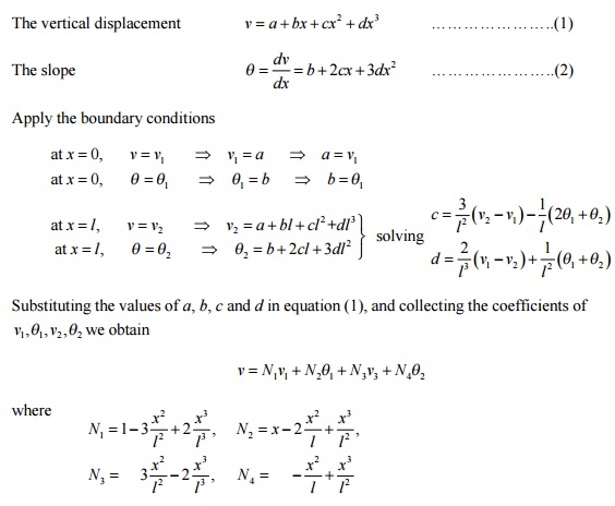
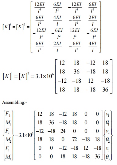
1-D 2-NODED CUBIC BE AM ELEMENT MATRICES
A single 1-d 2-noded c ubic beam
element has two nodes, with two degrees of freedom at each node (one vertic al
displacement and one rotation or slope). The re is a total of 4 dof and the
displacement polynomial function assumed should have 4 terms, so we choose a
cubic polynomial for the vertical deflection. Slope is a derivative of the
vertical deflections.
DEVELOPMENT OF ELEMENT EQUATION
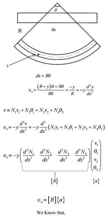
BEAM ELEMENT
A beam is a long, slender structural member
generally subjected to transverse loading that produces significant bending
effects as opposed to twisting or axial effects. An elemental length of a long
beam subjected to arbitrary loading is considered for analysis. For this
elemental beam length L, we assign two points of interest, i.e., the ends of
the beam, which become the nodes of the beam element. The bending deformation
is measured as a transverse (vertical) displacement and a rotation (slope).
Hence, for each node, we have a vertical displacement and a rotation (slope) – two
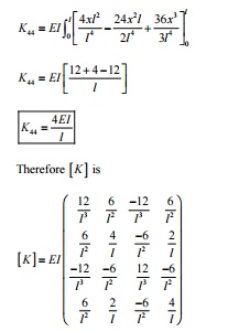
degrees of freedom at each node. For a single 2-noded beam element,
we have a total of 4 degrees of freedom. The associated “forces” are shear
force and bending moment at each node.
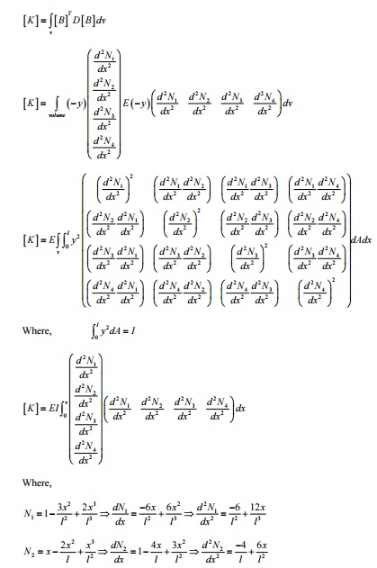
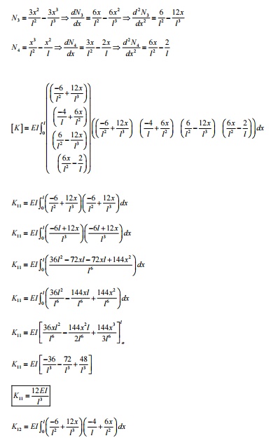
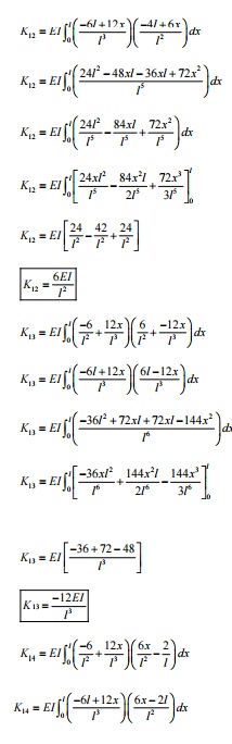
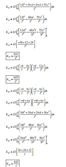
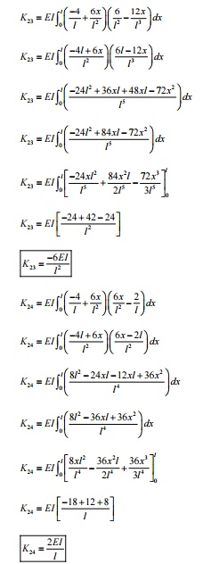
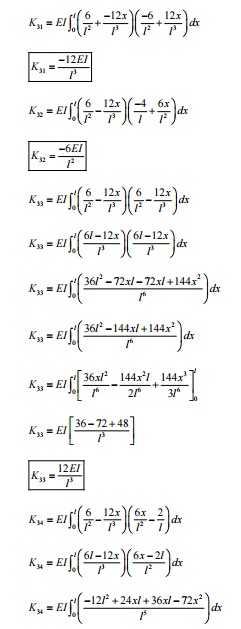
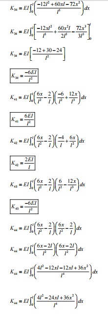
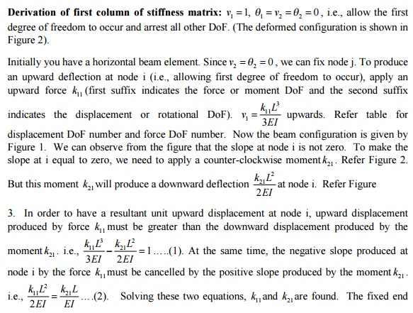
The stiffness term kij
indicates the force (or moment) required at i to produce a unit deflection (or
rotation) at j, while all other degrees of freedom are kept zero.
Sign
conventions followed
Upward
forces are positive and upward displacements are positive.
Counter-clockwise
moments are positive and counter-clockwise rotations are positive.
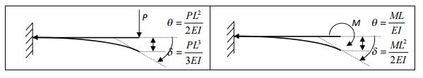
Formulae required –
cantilever beam subjected to concentrated load and moment.
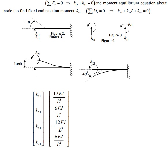
1 ELEMENT MATRICES AND VECTORS
reaction force and the reaction
moment are assumed to be acting upwards and counterclockwise, respectively. Now
use force equilibrium equation to find fixed end reaction force k ….…
Derivation of second column of
stiffness matrix:
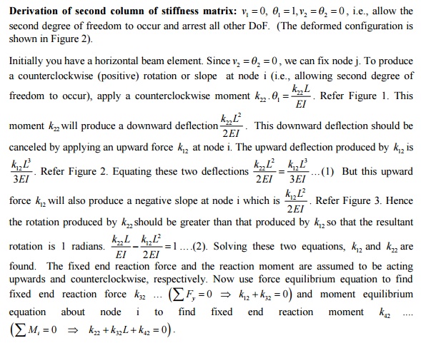
found. The fixed end reaction
force and the reaction moment are assumed to be acting upwards and
counterclockwise, respectively. Now use force equilibrium equation to find
fixed end reaction force
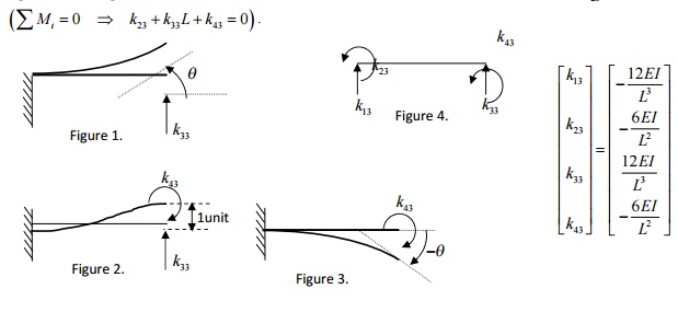
Derivation of third column of
stiffness matrix:
Derivation of third column of
stiffness matrix: v1 = 0, q1
=0,
v2 1,= q 2 0 , i.e., allow the third degree of
freedom to occur and arrest all other DoF. (The deformed configuration is shown
in Figure 2).
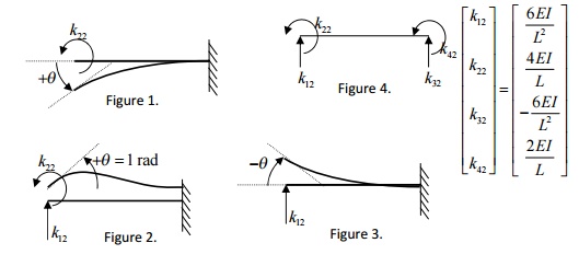
Initially you
have a horizontal beam element. Since V1=q1=0 we can fix node i. To produce an upward deflection
at node j (i.e., allowing third degree of freedom to occur), apply an upward
force k33 .

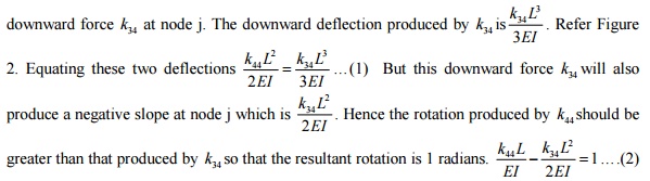
upwards. Now the beam configuration is given by
Figure 1. We can observe from 3EI
![]()
the figure that the slope at node
j is not zero. To make the slope at j equal to zero, we need to apply a
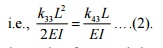
clockwise moment k43 . Refer Figure 2. But this moment k43
will produce a downward 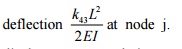
at node j. Refer Figure 3. In
order to have a resultant unit upward 2EI displacement at node j, upward
displacement produced by force k33 must be greater than the

same time, the positive slope
produced at node j by the force k33 must be cancelled by the negative slope
produced by the moment k43
Solving these two equations, k33
and k43 are found. The fixed end reaction force and the reaction moment are
assumed to be acting upwards and counterclockwise, respectively. Now use force
equilibrium equation to find fixed end reaction force 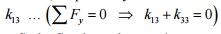 and moment equilibrium equation
about node i to find fixed end reaction moment k23
....
and moment equilibrium equation
about node i to find fixed end reaction moment k23
....
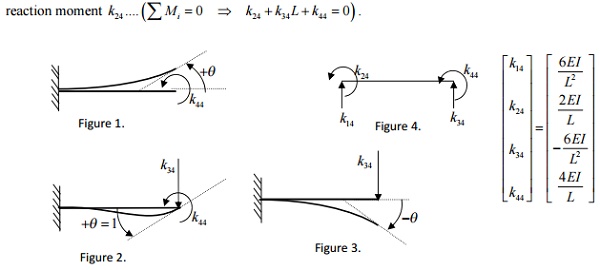
Derivation of fourth column of
stiffness matrix:
 fourth degree of
freedom to occur and arrest all other DoF. shown in Figure 2).
fourth degree of
freedom to occur and arrest all other DoF. shown in Figure 2).

i.e., allow the (The deformed configuration is shown in fig.
Initially you have a horizontal beam element.
Since  , we can fix node i.
To produce a counterclockwise (positive) rotation or slope at node j (i.e., allowing fourth degree of
freedom to occur), apply a
counterclockwise moment k44 . Refer Figure 1. This moment k44 will produce
a upward deflection
, we can fix node i.
To produce a counterclockwise (positive) rotation or slope at node j (i.e., allowing fourth degree of
freedom to occur), apply a
counterclockwise moment k44 . Refer Figure 1. This moment k44 will produce
a upward deflection ![]() This upward deflection should be canceled by applying
a
This upward deflection should be canceled by applying
a
Refer Figure 3. Solving these two
equations, k34 and k44 are found. The fixed end reaction force and the reaction
moment are assumed to be acting upwards and counterclockwise, respectively.
Now use force
equilibrium equation to find
fixed end reaction
force k14 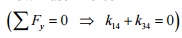 and moment equilibrium equation
about node i to find fixed end
and moment equilibrium equation
about node i to find fixed end
Problem
Find the slopes at the supports and support reac
beam shown in Figure-.4m4.
TakeDarylP4E=210-24LoganpageGPa,208I. = 2×10
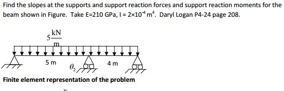
Finite element representation of the problem
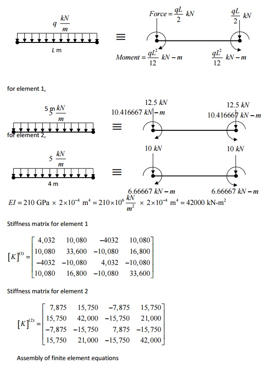
Conversion of UDL into nodal forces and nodal mo
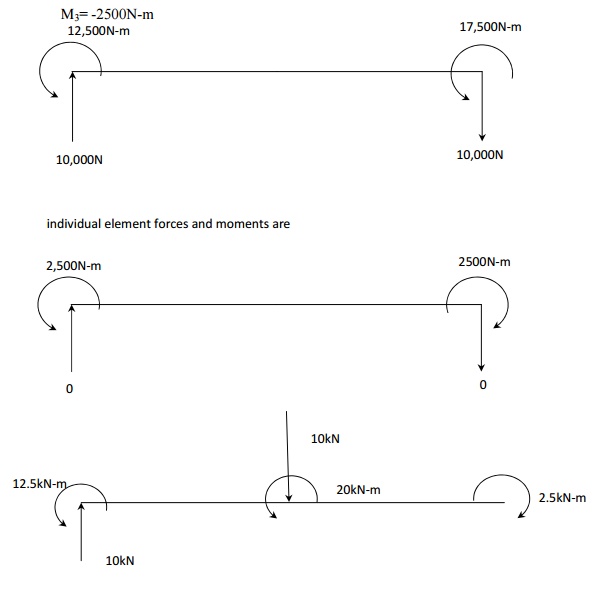
PROBLEM
Given that E=210 GPa and I=4×10 -4
m4, cross section of the beam is constant. Determine the deflection
and slope at point C. calculate the reaction forces and moments. DARYL LOGAN P
171-172
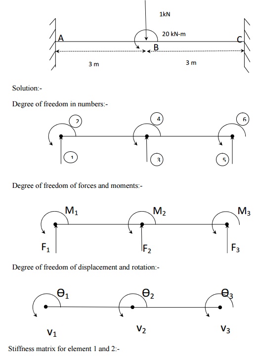
Boundary condition:-
F2=-10 kN; M2=20 kN-m
Therefore first, second, fifth, sixth columns are ineffective and hence
the reduced matrix is given by
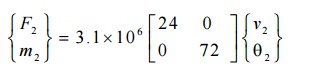
Deflection and slope at point c:-
V2= -1.34×10 -4
m = -0.134 mm
Ѳ2= 8.96×10
-5
rad
Reaction forces and moments:-
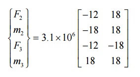
F1=10000N
M1=12500N-m
F3=0
M3=
-2500N-m
Related Topics