Chapter: Mechanical : Finite Element Analysis : One Dimensional Finite Element Analysis
One Dimensional Elements
ONE DIMENSIONAL ELEMENTS
Bar and beam elements are considered as One Dimensional elements. These elements are often used to model trusses and frame structures.
Ø Bar, Beam and Truss
Bar is a member which resists only axial loads. A beam can resist axial, lateral and twisting loads. A truss is an assemblage of bars with pin joints and a frame is an assemblage of beam elements.
Ø Stress, Strain and Displacement
Stress is denoted in the form of vector by the variablexasσx, Strain is denoted in the form of vector by the variable x as ex, Displacement is denoted in the form of vector by the variable x as ux.
Ø Types of Loading
(1) Body force (f)
It is a distributed force acting on every elemental volume of the body. Unit is Force / Unit volume. Ex: Self weight due to gravity.
(2) Traction (T)
It is a distributed force acting on the surface of the body. Unit is Force / Unit area. But for one dimensional problem, unit is Force / Unit length. Ex: Frictional resistance, viscous drag and Surface shear.
(3) Point load (P)
It is a force acting at a particular point which causes displacement.
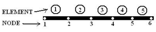
Ø Finite Element Modeling
It has two processes.
(1) Discretization of structure
(2) Numbering of nodes.
Ø CO – ORDINATES
(A) Global co –ordinates,
(B) Local co –ordinates and
(C) Natural co –ordinates.
Ø Natural Co – Ordinate (ε)
Integration of polynomial terms in natural co –ordinates for two dimensional elements can be performed by using the formula,
Shape function
N1N2N3 are usually denoted as shape function. In one dimensional
problem, the displacement
u = SNi ui =N1 u1
For two noded bar element, the displacement at any point within the
element is given by,
u = SNi ui =N1 u1 + N2 u2
For three noded triangular element, the displacement at any point
within the element is given by,
u = SNi ui =N1 u1 + N2 u2 + N3 u3
v = SNi vi =N1 v1 + N2 v2 + N3 v3
Shape function need to satisfy the following
(a) First derivatives should be finite within an element; (b) Displacement should
be continuous across the element boundary
Polynomial Shape function
Polynomials are used as shape function due to the following reasons, (1)
Differentiation and integration of polynomials are quite easy.
(2) It is easy to formulate and computerize the finite element equations.
(3) The accuracy of the results can be improved by increasing the order of
Ø Properties of Stiffness Matrix
1. It is a symmetric matrix,
2. The sum of elements in any column must be equal to zero,
3. It is an unstable element. So the determinant is equal to zero.
Ø Problem (I set)
1.A two noded truss element is shown in figure. The nodal displacements are u1 = 5 mm and u2 = 8 mm. Calculate the displacement at x = ¼ , 1/3 and ½ .
Ø Problem (II set)
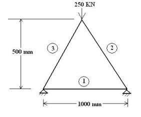
1. Consider a three bar truss as shown in figure. It is given that E = 2 x 10⁵
N/mm2. Calculate
(a) Nodal displacement,
(b) Stress in each member and
(c) Reactions at the support. Take Area of element 1 = 2000 mm2, Area of element 2 = 2500 mm2, Area of element 3 = 2500 mm2.
Ø Types of beam
1. Cantilever beam,
2. Simply Supported beam,
3. Over hanging beam,
4. Fixed beam and
5. Continuous beam.
Ø Types of Transverse Load
1. Point or Concentrated Load,
2. Uniformly Distributed Load and
3. Uniformly
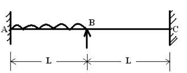
Ø Problem (III set)
1. A fixed beam of length 2L m carries a uniformly distributed load of w (N/m)
which runs over a lengt h of L m from the fixed end. Calculate the rota tion at Point
B.
LINEAR STATIC ANALYSIS( BAR ELEMENT)
Most structural analysis pro blems can be treated as linear static problems, b ased on the following assumptions
1.Small deformations (loading pattern is not changed due to the defor med shape)
2.Elastic materials (no plasticity or failures)
3.Static loads (the load is applied to the structure in a slow or steady fashion)
Linear analysis can pro vide most of the information about the behavior of a structure, and can be a good ap proximation for many analyses. It is also the ba ses of nonlinear analysis in most of th e cases.
Related Topics