Chapter: Optical Communication and Networking : Optical Networks
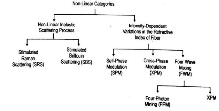
Non Linear Effects on Network Performance
Non Linear Effect on Network Performance
Important Challenges In Designing Non Linear Networks Are:
· Transmission of the different wavelength channel at the highest possible bit rate.
· Transmission over the longest possible distance with the smallest number of optical amplifier.
· Network architectures that allow simple and efficient operation, control and management.
The Various Signal Impairment Effect are as Follows
i. Group Delay Dispersion (GVD), Which limits the bit rate by temporally spreading a transmitted optical pulse, dispersion induced pulse spreading can be minimized by WDM networks operation in a low dispersion window such as 1310 nm and 1550 nm.
ii. Non-uniform gain across the desired wavelength range of EDFAs in WDM links.
iii. Polarization Mode Dispersion (PMD), Which arises from orthogonal polarization modes traveling at a slightly different speeds owing to fiber birefringence.
iv. Reflections from splices and connectors that can cause instabilities in laser sources. These can eliminated by the use of optical isolators.
v. Non-linear inelastic scattering processes, which are interactions between optical signal and molecular or acoustic vibrations in a fiber.
v. Non-linear variations of the refractive index in a silica fiber that occur because the refractive index is dependent on intensity changes in the signal.
· A connection request between modes A and B is blocked if one of the H intervening fibers is full.
· The probability Pb’ that a the connection request from A to B is blocked is the probabity and fiber link with all wavelength F.

· If q is the achievable utilization for a given blocking probability in a network with wavelength conversion.
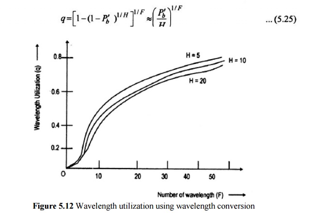
· The effect of path length is small, and q rapidly approaches I as F becomes large.
A Network Without Wavelength Conversion
· A connection request between A and B can be honoured only if there is a free wavelength.
· The probability Pb that the connection request from A and B is blocked is the probability that each wavelength is used on at least one of the H links,

· Letting P be the achievable utilization for a given blocking probability in a network without wavelength conversions,

· Where the approximation holds for large values of H and for Pb1/F not too close to unity.
· In this case, the achievable utilization is inversely proportional to the length of the path H between A and B.
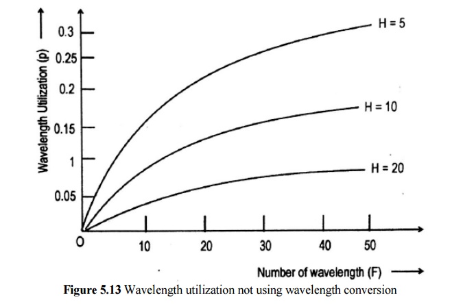
· Here the effect of path length (i.e., the number of links) is dramatic.
To Measure the Benefit of Wavelength Conversion
· The gain G=q/P to be the increase in fiber or wavelength utilization for the same blocking probability.
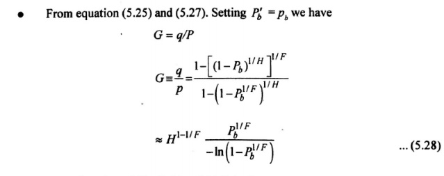
· G as a function of H=5, 10 and 20 links for blocking probability for pb=10-3.
· F increases, the gain increases, peaks at about H/2
· The gain slowly decreases, since large trunking networks are more efficient.
1. Effective Length And Area
· The non-linear process can be depend on the transmission length, the cross-sectional area of the fiber, and the optical power level in the fiber.
· Effective Length Leff: Which takes into account power adsorption along the length of the fiber (i.e., optical power decays exponentially with length) is given by

· When there is a optical amplifier in a link, the effective length is the sum of the effective lengths of the individual spans between optical amplifiers.
· If the total amplified link length is LA and the span length between amplifier is L, the effective length is

· The effects of non-linearities increase with the light intensity in a fiber. This light intensity is inversely propoetional to the cross-sectional area of the fiber.
· As a rule of thumb, standard non-dispersion-shifted single mode fibers have effective area Aeff=80μm2, dispersion-shifted fibers have effective area Aeff is 55μm2 and dispersion-compenstating fibers have effective areas is 20oμm2.
2. Stimulated Raman Scattering
· Stimulated Raman scattering is an interaction between light waves and the vibrational modes of silica molecules.
· If a photon with energy hv1 is incident on a molecule having a vibrational frequency vin, the molecule can absorb some energy from the photon.
· In interaction, the photon is scattered, thereby attaining a lower frequency v2 a corresponding lower energy hv2. The modified photon is called as stokes photon.
· The optical signal wave that is injected into a fiber is the source of the interacting photons, it is often called the pump wave, it supplies power from the generated wave.
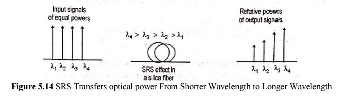
· SRS can severely limit the performance of a multichannel optical communication system by transferring energy from short-wavelength channels to neighboring higher-wavelength channels. This is a broadband effect that can occur in both dirctions.
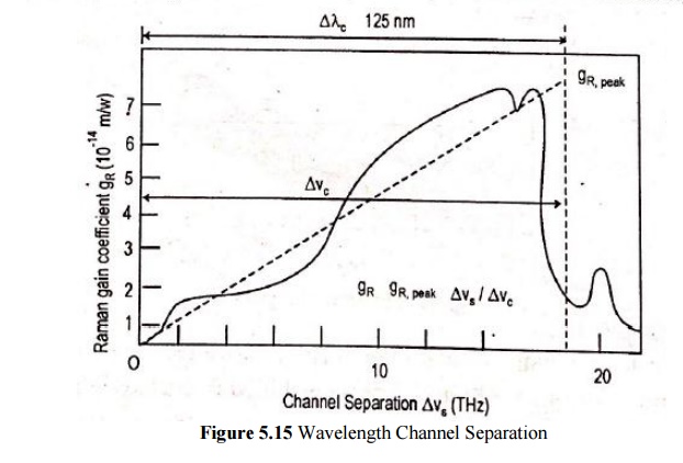
· The effects of SRS, consider WDM system has N channel equally spaced in a 30 nm band cantered at 1545 nm.
· Assume fout (j) is the fraction of power coupled from channel o to channel j
· The total fraction of power coupled out of 0 to all the other channel is
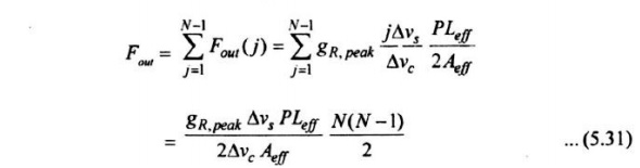
· The power penalty for this channel is -10 log(1-Fout)
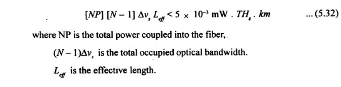
· To keep power penalty <0.5 dB and Fout <0.1 use equation (5.31) with Aeff=55μm2, the criterion.
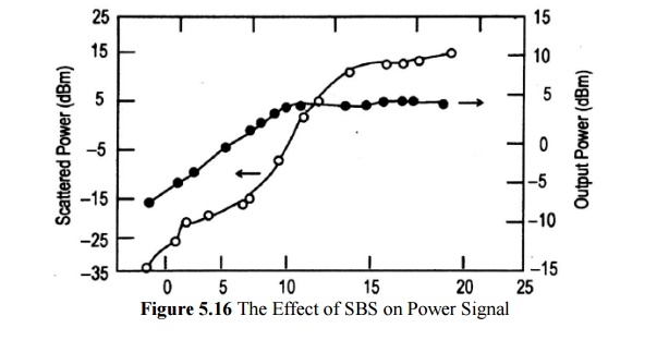
3. Stimulated Brillouin Scattering
· Stimulated Brillouin scattering arises when light waves scatter from acoustic waves.
· Scattered wave propagates principally in the backward direction in single-mode fibers. This backward light experiences gain from the forward-propagating signals.
· The frequency of the scattered light experiences a Doppler shift given by

Where n is the index refraction, Vs is the velocity of sound in material.
· Interaction occurs Brillouin linewidth of Dvg=20MHz at 1550nm.
· For Vs=5760 m/s in fused silica, the frequency of the backward propagating light at 1550 nm is shifted by 11 GHz(0.99nm) rom the original signal.
· In a long fiber chain containing optical amplifiers, there are optical isolators to prevent backward scattered signals form entering the amplifier.
· SBS threshold power Pth is defined to be the signal power at which the backward light equal the fiber-input power.
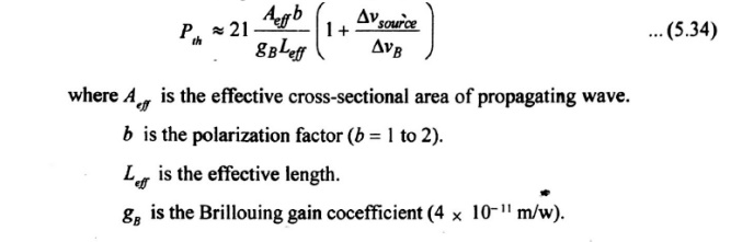
· The SBS threshold power increase as the source linewidth becomes larger.
· Several schemes are available for reducing the power penalty effects of SBS as follows:
- Keeping the optical power per WDM channel below the SBS thresholds, for long-haul systems.
- Increasing the linewidth of the source, smince the gain bandwidth of SBS is very small. This can be achieved through direct modulation of the source.
- Slightly dithering the laser output in frequency, at roughly tens of kilohertz. The dither frequency should scale as the ratio of the injected power to the SBS threshold.
4. Cross Talk
Crosstalk: it is defined us the feed through of one channel signal into another channel.
Types Of Crosstalk:
There are two types of crosstalk that can occur is WDM systems:
(1) Intrachannel crosstalk
(2) Interechannel crosstalk
(I)INTRACHANNEL CROSSTALK;
It arises when interfering signal is at the same wavelength as the desired signal. This effect is more severe than interchannel crosstalk, because the interference falls completely with in the receiver bandwidth.
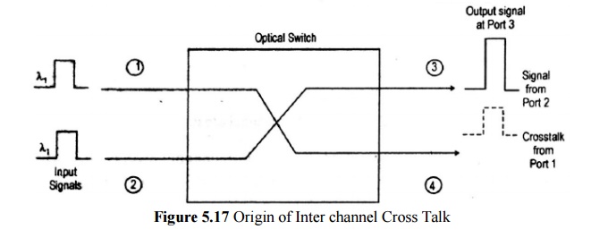
Two independent signals, each at a wavelength l1, enter an optical switch.
This switch routes the signal entering port 1 to output port 4, and routes the signal entering port 2 to output port 3.
Within the switch, a spurious fraction of the optical power entering port 1 gets coupled to port 3, where it interferes with the signal from port 2.
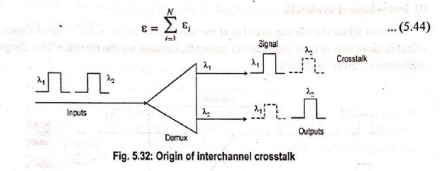
(II) INTERCHANNEL CROSSTALK
It arises when an interfering signal comes from a neighboring channel that operates at a different wavelength.
Power penalty of interchannel crosstalk is

Average crosstalk power eiP, the factor is from equation (5.43)
Example, a 1 –dB penalty arises when the intrachannel level is 38.7 dB below the signal level and for interchannel crosstalk is 16 dB below the signal.
Related Topics