Chapter: Optical Communication and Networking : Optical Networks
Broadcast and select WDM Networks
Broadcast and Select WDM Networks
· All-optical WDM networks have full potential of optical transmission capacity and versatility of communication networks beyond SONET architectures.
· These networks can be classified as
(1) Broadcast-and-select techniques
(2) Wavelength-routing networks.
· Broadcast-and select techniques employing passive optical stars, buses and wavelength routers are used for local networks can be classified as
(1) Single-hop networks
(2) Multi-hop networks
· Single hop refers to network where information transmitted in the form of light reaches its destination without being converted to an electrical form at any intermediate point. In a multi hop network, intermediate electro-optical conversion can occurred.
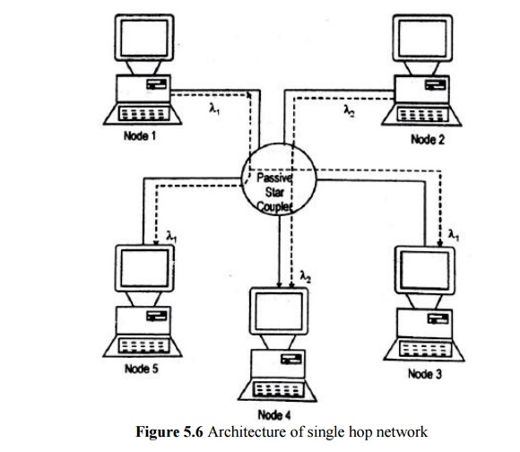
1. Broadcast and Select Signal Hop Network
· Two alternate physical architectures for a WDM-based local network have n sets of transmitters and receivers are attached to either a star coupler or a passive bus.
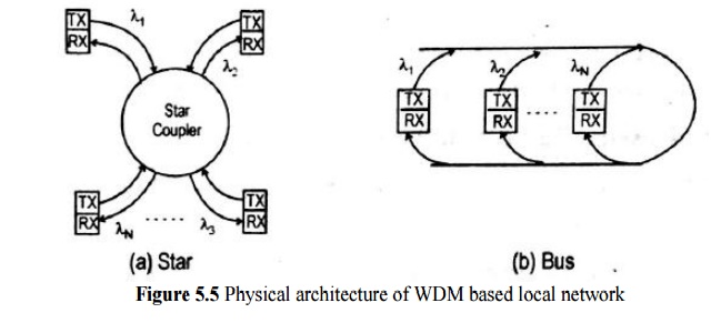
· Each transmitter sends its information at a fixed wavelength.
· All the transmissions from the various nodes are combined in a pasive star. Coupler or coupled onto a bus and sent out to all receivers.
· An interesting point to note is that the WDM setup is protocol transparent.
· Protocol transparent means that different sets of communicating nodes can use different information exchange rules (protocols) without affecting the other nodes in the network.
· The architectures of single-hop broadcast-and-select networks are fairly simple, there needs to be careful dynamic coordination between the nodes.
· A transmitter sends its selective filter to that wavelength.
· Two sending stations need to coordinate their transmission so tha collisions of information streams at the some wavelength do not occur.
2. Broadcast and Select Multihop Network
· Drawback of single-hop networks is the need for rapidlyt unable lasers or receiver optical fibers.
· This drawback can be overcome by the designs of multihop networks.
· Multihop networks do not have direct paths between each node pair.
· Each node has a small number of fixed tuned optical transmitter and receivers.
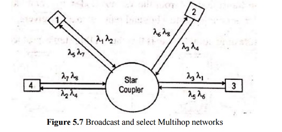
· An example, a four node broadcast and select multihop network where each node transmits on one set of two fixed wavelengths and receives on another set of two fixed wavelengths.
· Information destined for other nodes will have to be routed through intermediate stations.
· Considering the operation, a simplified transmission shceme in which message are sent as packets with a data field and an address header containing source and destination identifiers (i.e,. routing information) with control bits.
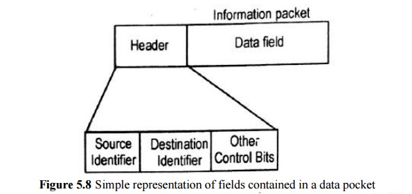
· At intermediate node, the optical signal is converted to an electrical format.
· The address header is decoded to examine the routing information field, which will indicate where the packet should go.
· Routing information is used to send the electronic packets from optical transmitter to the next node in the logical path toward its final destination.
· Advantage: There are no destination conflicts or packet collisions in the network.
· For H hops between nodes, there is a network throughput penalty of at least 1/H.
3. The Shuffle Net Multihop Network
· Various topologies for multihop lighwave networks are
(1) The shuffle net graph
(2) The de Bruijin graph
(3) He toroidal Manhattan street network
· A scheme called the perfect shuffle is widely used to form processor interconnect patterns in multiprocessors.
· For optical networks, the logical configuration consists of a cylindrical arrangement of k column, each having p nodes. Where P is the number of fixed transceiver pairs per node.
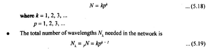
· The total number of nodes is then
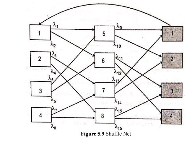
· a (p,k)=(2,2) shuffle net, where the (k+1)th column represents the completion of a trip around the cylinder back to the first column.
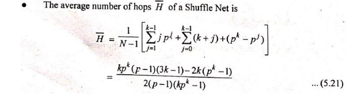
· Performance parameter for the shuffle net is the average number of hops between any randomly chosen nodes.
· Since, all nodes have p output wavelength, p nodes can be reached from any node in one hop, p2 additional nodes can be reached in two hope, until all the (pk-1) other nodes are visited.
· The maximum number of hops is

· Consider figure above, the connections between nodes 1 and 5 and nodes 1 and 7. In first case, the hop number is one.
· In second case three hops are needed with routes 1- 6 – 7 or 1 – 5 – 2 -7.?
· The average of hops Bar H of a shuffle net is
· In multiphopping, part of the capacity of a particular link directly connecting two nodes is actually utilized for carrying between them.
· The rest of thelink capacity is used to forward messages from other nodes.
· The system has Np=kpK+1 links, the total network capacity C is

· The per-user throughput δ is

· Different (p,k) combination result in different throughputs, to get a better network performance.
Related Topics