Chapter: Mobile Networks : Routing
Multicast in the Internet and Multicast routing
MULTICAST IN THE INTERNET
Some
applications require data to be delivered from a sender to multiple receivers.
Examples of such applications include audio and video broadcasts, real-time
delivery of stock quotes, and teleconferencing applications. A service where
data is delivered from a sender to multiple receivers is called multipoint
communication or multicast, and applications that involve a multicast delivery
service are called multicast applications.
Bellow
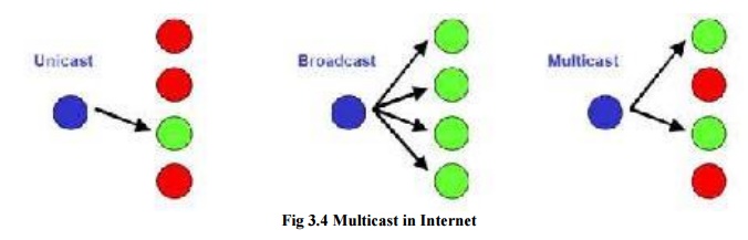
Figure compares multicast to other communication paradigms. In unicast or
point-to-point communication, data is sent to a single host. In broadcast or
one-to-all communications, data is transmitted to all hosts with respect to a
given scope, for example, all hosts in a LAN. Multicast can be thought of as a
generalization of unicast and broadcast. In multicast, data is transmitted to a
set of hosts that have indicated interest in receiving the data, referred to as
a multicast group or host group.
In
principle, it is feasible to implement multicast in a network using either
unicast or broadcast. However, both solutions have shortcomings. In a unicast
solution to multicast, the sender transmits one copy of the data separately to
each host in the multicast group. This is viable for small multicast groups,
but when the number of hosts is large, transmitting the same data multiple
times wastes a lot of resources. In a broadcast solution to multicast, data is
delivered to all hosts in a network; for example, and hosts drop the data if
they are not members of the multicast group. This solutions works when the
hosts of a multicast group are all located on the same LAN and the LAN supports
broadcast transmissions. Otherwise, sending data to a large number of hosts
just to have it dropped by most hosts is not an economical use of network
capacity.
Making
multicast delivery efficient in a packet switching network requires a whole set
of new protocols and mechanisms at the network layer. First, multicast
addresses must be available that can designate a multicast group as the
destination of a datagram. Second, there must be mechanisms that allow a host
to join and leave a multicast group. Third, there is a need for multicast
routing protocols that set up paths, called distribution tree, from the sender
to the members of a multicast group. The issues related to setting up multicast
distribution trees are referred to as multicast routing.
The
network-layer mechanisms in the Internet that support multicast are referred to
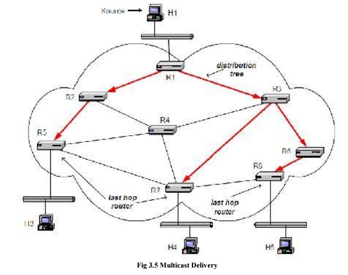
as IP multicast. Figure depicts an example of multicast in an IP network. The
figure shows four hosts and eight routers. Routers are connected by
point-to-point links and hosts connect to routers via Ethernet LANs. Host H1 is
a source of multicast data, and hosts H2, H3 and H4 are Multicast receivers.
The distribution tree, indicated with arrows, is established by the routers
using a multicast routing protocol. Data is delivered downstream in the
distribution tree from the source to the receivers.
IP
multicast involves both hosts and routers. In IPv4, support of IP mult icast is
optional, but almost all hosts and most routers support multicast. Hosts that
are members of a multicast group exchange Internet Group Management Protocol
(IGMP) messages with routers. Routers perform two main processes in IP
multicast: multicast routing and multicast forwarding. Multicast routing sets
up the distribution tree for a multicast group by setting the content of
multicast routing tables. In multicast, a routing table may list multiple next
hop addresses for a routing table entry. As in unicast, forwarding refers to
the processing of an incoming datagram, the routing table lookup, and the
transmission on an outgoing interface. When a multicast packet arrives at a
router, the router performs a lookup in the multicast routing table for a
matching entry. The router forwards one copy of the packet to each next hop
address in the matching routing table entry.
1. MULTICAST ROUTING
Multicast
routing is concerned with setting up distribution trees that provide a path
from the multicast sources to multicast group members. This section discusses
the objectives of multicast routing, and the protocol mechanisms used in
routing protocols.
a) Multicast Routing Algorithms in a Graph
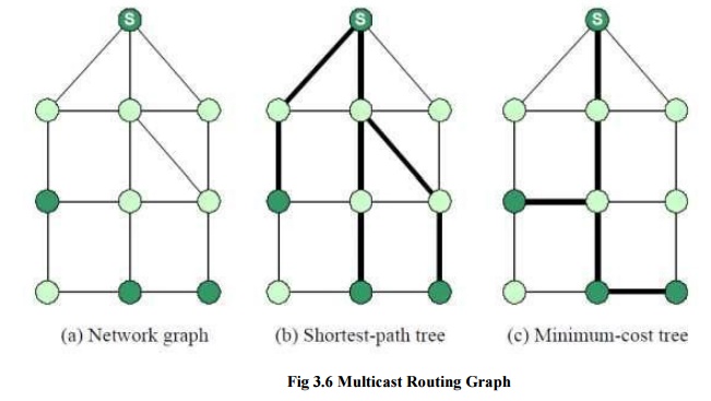
In this
graph, the task of multicast routing is the embedding of a tree into the graph
such that all multicast group members are connected by the tree. So, how would
an ideal embedding look like? One can think immediately of two objectives to
build a good tree, which are shown. In the figures, the thick lines indicate
the distribution trees. The first objective is to build a tree that minimizes
the path cost from the source to each receiver. Such a tree is called a
shortest-path tree or source-based tree. A shortest-path tree can be relatively
quickly computed using a shortest-path algorithm, but has the drawback that the
tree is dependent on the source of the multicast tree. Note in figure, that the
shortest-path tree is different when a different node is the source in the
multicast group. Therefore, a distribution tree must be computed separately for
each source. The second objective is to build a tree that minimizes the total
cost of the edges, called a minimum-cost tree.
Different
from a shortest-path tree, a minimum-cost tree does not change when a different
node becomes the source. Thus, the same tree can be shared by all sources. The
main drawback of a minimum-cost tree is that its computation is prohibitively
expensive in most cases. In fact, the problem of calculating a minimum-cost
tree is known to be an NP-complete problem, meaning that the computation of the
tree is intractable unless the network is small. The two objectives for
multicast routing, shortest-path tree and minimum-cost tree, represent a set of
trade-off for multicast routing. Shortest-path trees minimize the cost of each
receiver, whereas the minimum-cost tree minimizes the cost of the total tree. A
single minimum-cost tree can be shared by all senders, whereas, a shortest-path
trees must be built for each source. Lastly, a shortest-path tree can be
computed relatively quickly, whereas the computation of a minimum cost-tree is
not tractable in large networks. Some of the above trade-offs of multicast
routing are reflected in the multicast routing protocols for the Internet.
However, routing protocols have to satisfy additional constraints, which are
not expressed in the formulation of a graph problem. For example, routing
protocols must be able to adapt the distribution tree quickly when hosts join
and leave a multicast group. Additionally, most multicast routing protocols require
computing the distribution tree in a distributed fashion without any central
coordination. Finally, most multicast routing protocols try to leverage off
unicast routing protocols, by constructing the distribution tree using
information from the unicast routing tables. This imposes additional
constraints on a multicast routing protocol.
b) Reverse Path Forwarding
The
majority of routing protocols in the Internet built either source-based trees
or core-based trees. A source-based tree is essentially a shortest-path tree,
with a multicast source at the root of the distributions tree. With
source-based trees, one distribution tree must be built for each multicast
source. Protocols that built core-based trees avoid the need for multiple
distribution trees by building a single distribution tree that is shared by all
sources. Core-based tree routing protocols do not attempt to construct a
minimum-cost tree. Instead, one router is selected as core or rendezvous-point,
and a shortest-path tree is constructed with the core router as the root of the
tree. Thus, both source-based trees and core-based trees build shortest path
trees. For reasons that will become clear in a moment, routing protocols
generally minimize the paths from the receivers to the source, as opposed to
minimizing the path from the source to the receiver.
A reverse
shortest path tree can be built by applying a concept called reverse path
forwarding (RPF). RPF is a mechanism to build a shortest path tree in a
distributed fashion by taking of the unicast routing tables. The idea of RPF is
simple. Given the address of the root of the tree, a router selects as its
upstream neighbor in the tree of the router which is the next-hop neighbor for
forwarding unicast packets to the root. The network interface which is used to
reach this upstream neighbor is called the RPF interface and the neighbor
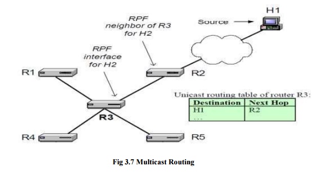
router is called the RPF neighbor. An illustration of the basic concept of
reverse path forwarding is given in Figure 10.12. Here, host H1 is the root of
the distribution tree. Router R3 determines that R2 is its RPF neighbor for H1
from a lookup in its routing table. The interface that connects to R2 is the
RPF interface.
If all
routers determine their upstream neighbor using reverse path forwarding, the
resulting distribution tree is such that packets from the root to a receiver
are forwarded on the reverse path taken by unicast packets sent from the
receiver to the root. This is where the name reverse path forwarding comes
from. Since unicast routing tables are set so that the path from the receiver
to the root is minimal, the tree generated by reverse path forwarding is a
reverse shortest path. Reverse path forwarding is applied to construct
source-based, as well as core-based trees. In the former case, the root of the
tree is a multicast source. In the latter case, the root of the tree is the
core.
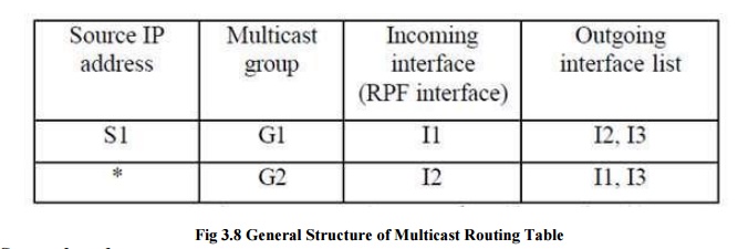
The
general structure of a multicast routing table is shown in Figure 10.13. There
are columns for a source IP address, a multicast address, an incoming interface
and a list of outgoing interfaces. Routing table entries for source-based trees
and for core-based trees are different. In a source based tree, a routing table
entry contains a source address as well as a group address. This is often
called a (Source, Group) or (S, G) entry. Since a source-based tree has one
distribution tree for each source there may be multiple routing entries for the
same multicast group. Routing table entries for a core-based tree do not list a
source IP address, which is indicated with a ‗*‘
(star) in
the source IP address column. The corresponding entry is called a (*, G) entry.
In an (S, G) entry, the incoming interface entry is the RPF interface for
address S. In an (*, G) entry, the incoming interface is set to the RPF interface
with respect to the core.
An
arriving multicast packet must match the source address and the group address
in an (S, G) entry, and the group address in an (*, G) entry. If there are
matches for both (S, G) and (*, G) entries, the (S, G) entries take preference.
When a match is found in the routing table, the router verifies that the packet
arrived on the incoming interface listed in the incoming interface column of
the routing table. This is called an RPF check. If an RPF check is successful,
one copy of the datagram is forwarded on each interface listed in the outgoing
interface list. If there is no match in the routing table or if the RPF check
failed, the packet is discarded.
Source-based trees
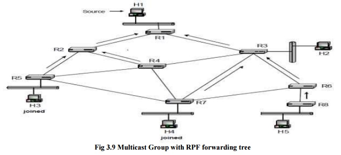
We
illustrate the construction of a source-based tree for the network shown in
Figure. Each host is connected to a router via an Ethernet network and routers
are connected by point to point links. H1 is the source of a multicast group
and hosts H3 and H4 are receivers that have joined the multicast group. The
arrows in the figure indicate the reverse shortest paths for all routers in the
network. Data transmissions in the source-based distribution tree for H1 follow
the opposite direction of the reverse shortest paths. The paths for H3 and H4
are H1à R1à R2 à R5 à H3 and H1à R1à R3 à R7 à H4, respectively.
Since the
RPF interface tells each router the upstream neighbor in the distribution tree,
but not the downstream neighbors in a distribution tree, additional protocol
mechanisms are needed to determine the outgoing interfaces in the multicast
routing tables. One method to achieve this is flood-and-prune, which starts out
by forwarding multicast packets on all its interfaces, and then deletes
interfaces which are not part of the distribution tree. Another method, called
explicit join, requires that multicast receivers initiate the process of
getting connected to the distribution tree. We will describe both methods.
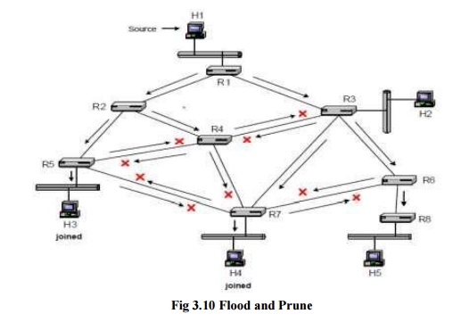
In
flood-and-prune, the outgoing interface list in a routing table entry initially
lists all interfaces other than the RPF interface. When a router receives a
multicast packet from source address S for a multicast group G, on the RPF
interface for source S, it forwards the packet on all interfaces, with
exception of the RPF interface. When a router receives a packet on an interface
that is different from the RPF interface for S, it discards the packet. Figure
10.15 shows how multicast packets from H1 are forwarded with this method.
Arrows indicate the transmission of packets and crosses show where packets are
discarded. Figure 10.15 show that due the flooding of messages, many routers
receive multiple copies of the same packet. All but the copy arriving on the
RPF interface are discarded. A router connected to a LAN, forwards a datagram
to the LAN only if some hosts on the LAN are multicast group members. In Figure
10.15, these are the LANs where the multicast group members H3 and H4 reside. A
router knows about group members on a LAN from IGMP messages.
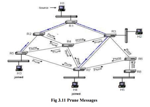
In Figure
when hosts H3 and H4 want to receive multicast packets from source S for group
G, the connected routers, R5 and R7, send a join message to the router on their
RPF interfaces. When a router receives a join message, it adds the interface
where the join message was received to the list of outgoing interfaces of the
(S, G) routing table entry. If an (S, G) routing entry does not exist, it will
be created when the join message arrives. In Figure 10.18, when R2 receives a
join message from R5, it adds the interface that connects to R5 to the outgoing
interface list. As with graft messages, a router forwards a join message on its
RPF interface only if the router is not part of the distribution tree.
When a
router in the distribution tree receives a join message, it does not forward
the join message. This method of explicit join messages avoids the transmission
of duplicate packets as in flood-and-prune. On the other hand, building
source-based trees with explicit join messages assume that routers know the identity
of hosts that transmit to a multicast group.
Routing
protocols that built core-based trees designate a router, called the core, and
built a reverse shortest path tree with the core as the root of the tree. The
core becomes the central hub for disseminating multicast packets sent to the
group. When a source transmits a packet to a multicast group, the packet is
sent to the core. When the packet reaches the core, it is forwarded using the
reverse shortest path tree.
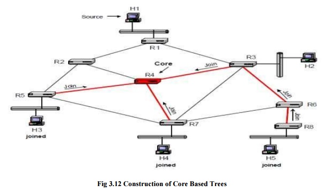
The
construction of a core-based tree for a multicast group G is illustrated in
Figure. Each receiver that joins a multicast group sends a join message to the
core router of the group. The message is sent on the RPF interface with respect
to the core. If the join message reaches a router that is not part of the tree,
the router adds an (*, G) entry to the multicast routing table, adds the
interface where the join message arrived to the outgoing interface list, and
sets the incoming interface to the RPF interface. Then, the router forwards the
join message on its RPF interface in the direction of the core. If the router
is already part of the shared tree for group G, the router, upon receiving a
join message, adds the interface where the join message arrived to the outgoing
interface list of the corresponding (*, G) entry, but does not forward the join
message. Since join messages are sent on the reverse shortest path, the
resulting distribution tree is a reverse shortest-path tree rooted at the core.
The Figure illustrates the transmission of join messages with router R4 as
core, and hosts H3, H4, and H5 has members of the multicast group.
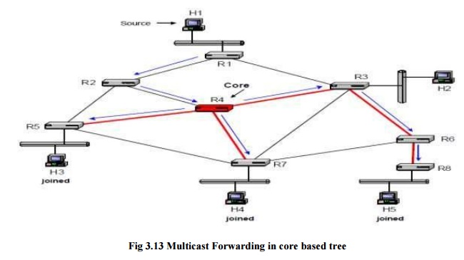
Forwarding
of multicast packets in core-based trees is illustrated in Figure. When H1
transmits a multicast packet, the packet is forwarded on the unicast shortest
path to the core. A possible route is H1à R2 à R4. When the packet reaches the
tree at the core, it is sent downstream in the core-based tree. Sending packets
always to the core and inserting packets into the distribution tree only at the
core can be inefficient. For example, suppose the path from R1 to R4 is through
R3. Then, a packet from H1 to H5 takes the route H1à R1 à R3 à R4 à R3 à à R6 à
R8. Here, it would be better to have R3, instead of forwarding the packet to
the core, forward the datagram using the core-based tree. R3 should forward the
datagram downstream the tree to R6, as well as upstream the tree to R4.
However, such bidirectional trees, where packets are forwarded both upstream
and downstream a core-based tree, are prone to routing loops, and special
precautions are necessary to avoid such loops.
The main
advantage of using core-based trees is that only one distribution tree is
required for each multicast group. This reduces the complexity of the routing
tables, as well as the volume of multicast routing protocol messages. The main
disadvantage of core-based trees is that, dependent on the placement of the
core, the paths from the sender to the receivers through the core can be much
longer than the direct path between a source and a receiver.
Overview of Multicast Routing Protocols
Here is a
brief overview of the multicast routing protocols that have been developed for
the Internet. Distance Vector Multicast
Routing Protocol (DVMRP):5 DVMRP was the first multicast routing protocol
developed for the Internet. DVMRP can operate in an environment where some, but
not all routers in the network are capable of multicast forwarding and routing.
This is achieved by having DVMRP run a separate unicast routing algorithm,
similar to RIP, to determine the shortest-paths between all multicast-capable
routers. DVMRP uses flood-and prune to set up source-based trees. DVMRP
messages are encapsulated in IGMP messages, where the type field is set to 3.
DVMRP
played an important role in the early deployment of IP multicast. IP multicast
deployment in the Internet began in the early 1990s with the creation of the
Multicast Backbone (MBONE). The multicast routing algorithm in the MBONE is
DVMRP. The MBONE solved the problem of wide-area IP multicast routing on the
Internet where only few routers were capable of IP multicast routing, by
setting up a virtual network of multicast routers that are connected by unicast
path. These multicast routers exchanged multicast IP datagram that were
encapsulated in IP unicast datagrams, using the IP-in-IP option in the IP
header.
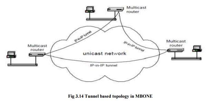
As a
result of the encapsulation, the MBONE is a virtual network, where each link
between two multicast routers consists of a complete unicast path. As more and
more routers provide native support for IP multicast, meaning that they are
capable of forwarding IP multicast traffic and running a multicast routing
protocol, the need for a virtual multicast network has all but disappeared. Multicast Open Shortest Path First
(MOSPF):6 MOSPF consists of multicast extensions to the unicast routing
protocol OSPF, and requires that OSPF is used for unicast routing. In MOSPF,
multicast routers broadcast link state advertisements (LSAs) to all other
multicast routers. Then, as in unicast OSPF, each multicast router calculates
routes independently.
MOSPF
computes shortest-path trees for each sender in the multicast group. A router
computes a shortest-path tree for a source only if there is traffic from that
sender. Core Based Tree (CBT):7 CBT was the first routing protocol for the Internet that
took a corebased tree approach. CBT
builds a shared tree using reverse-path forwarding, without making assumptions
on the unicast routing protocol used. The core of a group is either statically
configured, or determined as the outcome of a selection process from a
candidate set. Different multicast groups may use different core-bases trees.
Distribution trees in CBT are bidirectional, that is, routers are capable of
forwarding multicast packets downstream away from the core as well as upstream
towards the core.
Protocol Independent Multicast (PIM):8
Protocol independent multicast consists of
two multicast routing protocols: PIM Dense Mode (PIM-DM) and PIM Sparse
Mode (PIM-SM). PIM-DM builds source-based trees using flood-and-prune, and is
intended for large multicastence of this is that PIM must assume that all
routers in the network are multicast enabled. An important difference between
the core-based trees of PIM and CBT is that the trees in PIM are
unidirectional, that is, sources always forward packets to the core, and the
core transmits packets downstream the corebased tree.
All of
the above multicast routing protocols follow the service model of IP multicast
where any host can transmit to all multicast groups. Since this service model
makes multicast routing complex, recently there has been support for a
source-specific multicast service model, where hosts join a multicast group
separately for each source. This service model is called Source- Specific
Multicast (SSM). SSM requires that a host, when it joins a multicast group G,
also specifies the source S from which it wishes to receive multicast packets.
This can be accommodated by IGMPv39, a recently completed new revision IGMP,
which allows hosts to join a multicast group for specific sources. SSM does not
require new multicast routing protocols. In fact, routing for SSM can be
realized with a subset of most existing protocols.
Related Topics