Chapter: Electrical machines : DC Generators
Methods of Excitation used for DC Generator
Methods of Excitation used for DC Generator
The magnetic field required for the operation of a d.c. generator is produced by an electromagnet. This electromagnet carries a field winding which produces required magnetic flux when current is passed through it.
The field winding is also called exiting winding and current carried by the field winding is called an exciting current.
Thus supplying current to the field winding is called excitation and the way of supplying the exciting current is called method of excitation.
There are two methods of excitation used for d.c. generators.
1. Separate excitation
2. Self excitation
Depending on the methods of excitation used, the d.c. generators are classified as,
1. Separately excited generator
2. Self excited generator
In separately excited generator, a separate external d.c. supply is used to provide exciting current through the field winding.
The d.c. generator produces d.c. voltage. If this generated voltage itself is used to excite the field winding of the same d.c. generator, it is called self excited generator.
1. Separately Excited Generator
When the field winding is supplied from external, separate d.c. supply i.e. excitation of field winding is separate then the generator is called separately excited generator. Schematic representation of this type is shown in Fig 7.39.
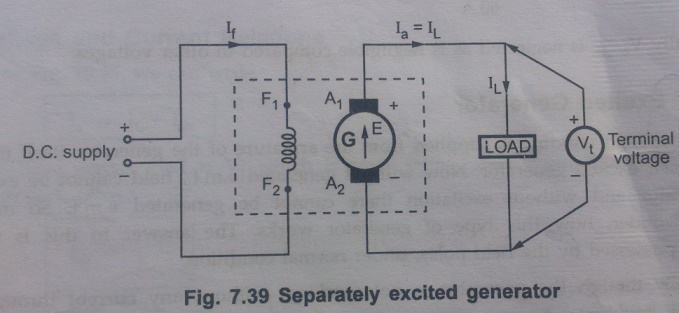
The field winding of this type of generator has large number of turns of thin wire. So length of such winding is more with less cross-sectional area. So resistance of this field winding is high in order to limit the field current.
Voltage and current Relations
The field winding is excited separately, so the field current depends on supply voltage and resistance of the field winding.
For armature side, we can see that it is supplying a load, demanding a load current of IL at a voltage of Vt which is called terminal voltage.
Now Ia = IL
The internally induced e.m.f. E is supplying the voltage of the load hence terminal voltage Vt is a part of E is not equal to Vt while supplying a load. This is because when armature current Ia flows through armature winding, due to armature winding resistance Raohms, there is a voltage drop across armature winding equal to IaRa volts. The induced e.m.f. has to supply this drop, along with the terminal voltage Vt. To keep Ia Ra drop to minimum, the resistance Ra is designed to be very small. In addition to the drop, there is some voltage drop at the contacts of the brush called brush contact drop. But this drop is negligible and hence generally neglected. So in all, induced e.m.f. E has three components namely,
i) Terminal voltage Vt
ii) Armature resistance drop IaRa
iii) Brush contact drop Vbrush
So voltage equation for separately excited generator can be written as,
E = Vt + IaRa + Vbrush
Where E = ϕPNZ / 60A
Generally Vbrush is neglected as is negligible compared to other voltages.
2. Self Excited Generator
When the field winding is supplied from the armature of the generator itself then it is said to be self excited generator. Now without generated e.m.f., field cannot be excited in such generator and without excitation there cannot be generated e.m.f. So one may obviously wonder, how this type of generator works. The answer to this is residual magnetism possessed by the field poles, under normal condition.
Practically though the generator is not working, without any current through field winding, the field poles possess some magnetic flux. This is called residual flux and the property is called residual magnetism. Thus when the generator is started, due to such residual flux, it develops a small em.f. which now drives a small current through the field winding. This tends to increase the flux produced. This in turn increases the induced e.m.f. This future increases the field current and the flux. The process is cumulative and continuous till the generator develops rated voltage across its armature. This is voltage building process in self excited generators.
Based on how field winding is connected to the armature to derive its excitation, this type is further divided into following three types.
i) Shunt generator
ii) Series generator
iii) Compound generator
Let us see the connection diagram and voltage, current relations or these types of generators.
i. Shunt Generator
When the field winding is connected in parallel with the armature and the combination across the load then the generator is calledshunt generator.
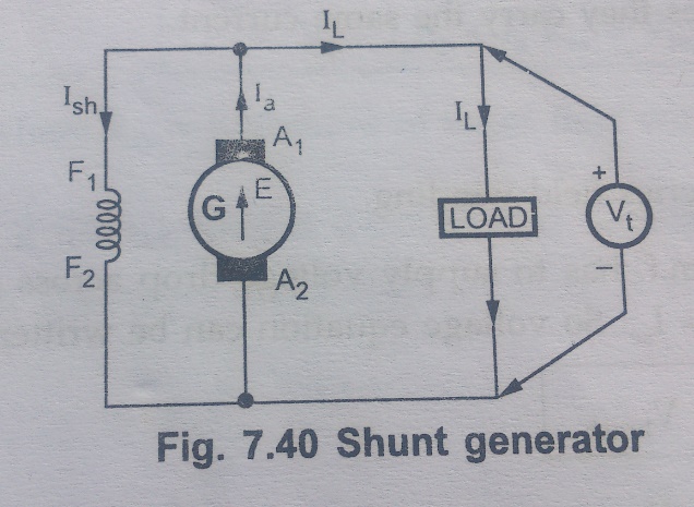
The ield winding has large number of turns of thin wire so it has high resistance. Let Rsh be the resistance o the field winding.
Voltage and Current Relations
From the Fig. 10. 45 , we can write
Ia = IL + Ish
Now voltage across load is Vt which is same across field winding as both are in parallel with each other.
Ish = Vt / Rsh
While induced e.m.f. E, still required to supply voltage drop IaRa and brush contact drop.
E = Vt + IaRa + Vbrush
E = ϕPNZ / 60A
In practice, brush contact drop can be neglected.
ii. Series Generator
When the field winding is connected in series with the armature winding while supplying the load then the generator is called series generator.
It is shown in the Fig. 7.41.
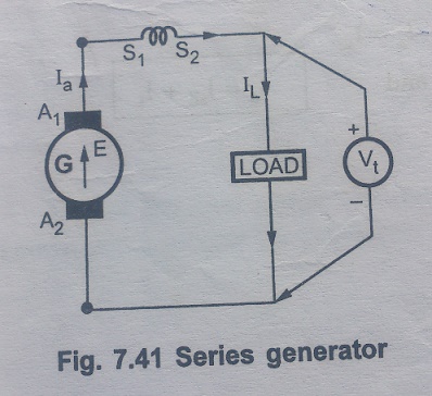
Field winding, in this case is denoted as S1 and S2. The resistance of series field winding is very small and hence naturally it has less number of turns of thick cross-section wire as shown in the fig,7.41.
Let Rse be the resistance of the series field winding
Voltage and Current Relations
As all armature, field and load are in serious they carry the same current.
Ia = Ise = IL
Where Ise = Current through series field winding
Now in addition to drop IaRa, induced e.m.f. has to supply voltage drop across series field winding too. This is IseRse i.e. IaRse as Ia = Ise. So voltage equation can be written as,
E= Vt + IaRa + IaRse + Vbrush
E= Vt + Ia (Ra + Rse ) + Vbrush
Where E = ϕPNZ / 60A
iii. Compound Generator
In this type, the part of the field winding is connected in parallel with armature and part in series with the armature. Both series and shunt field windings are mounted on the same poles. Depending upon the connection of shunt and series field winding, compound generator is further classified as :
a) Long shunt compound generator,
b) Short Shunt compound generator
a) Long shunt compound generator,
In this type, shunt field winding is connected across the series combination of armature and series combination of armature and series field winding as shown in the Fig. &.42.
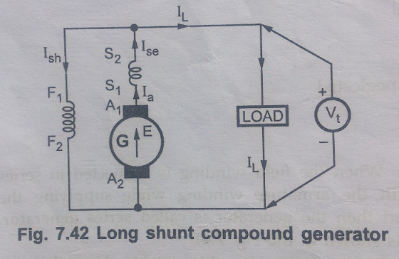
Voltage and current relations are as follows.
From the ig. 7.42
Ia = Ise
and
Ia = Ish + IL
Voltage across shunt field winding is Vt.
Ish = Vt / Rsh
Where Rsh = Resistance of shunt field winding.
And voltage equation is,
E = Vt + IaRa + IaRse + Vbrush
Where Rse = Resistance of series field winding.
b) Short Shunt compound generator
In this type, shunt field winding is connected, only across the armature excluding series field winding as shown in the Fig.7.43.
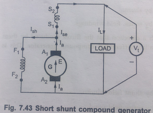
Voltage and current relations are as follows.
For the Fig. 7.43, Ia = Ise + Ish
Ise = IL
Ia = IL + Ish
The drop across shunt field winding is drop across the armature only and not the total Vt, int his case. So drop across shunt field winding is E – IaRa.
Ish = E-IaRa / Rsh
Now the voltage equation is E = Vt + Ia Ra + IseRse + Vbrush
Ise = IL
E = Vt + IaRa + IL Rse + Vbrush
Neglecting Vbrush, we can write,
E = Vt + IaRa + IL Rse
E - IaRa = Vt + IL Rse
Ish = [Vt + ILRse] / Rsh
Any of the two above expressions of Ish can be used, depending on the quantities known while solving the problems.
Related Topics