Chapter: Electrical machines : DC Generators
DC Generator Characteristics
Generator Characteristics
The three most important characteristics or curves of a D.C generator are:
1. Open Circuit Characteristic(O.C.C.)
This curve shows the relation between the generated emf. at no-load (E0) and the field current (If) at constant speed. It is also known as magnetic characteristic or no-load saturation curve. Its shape is practically the same for all generators whether separately or self-excited. The data for O.C.C. curve are obtained experimentally by operating the generator at no load and constant speed and recording the change in terminal voltage as the field current is varied.
2. Internal or Total characteristic (E/Ia)
This curve shows the relation between the generated emf. On load (E) and the armature current (Ia). The emfE is less than E0 due to the demagnetizing effect of armature reaction. Therefore, this curve will lie below the open circuit characteristic (O.C.C.)It cannot be obtained directly by experiment. It is because a voltmeter cannot read the emf. Generated on load due to the voltage drop in armature resistance. The internal characteristic can be obtained from external characteristic if winding resistances are known because armature reaction effect is included in both characteristics.
3. External Characteristic (V/IL)
This curve shows the relation between the terminal voltage (V) and load current (IL). The terminal voltage V will be less than E due to voltage drop in the armature circuit. Therefore, this curve will lie below the internal characteristic. This characteristic is very important in determining the suitability of a generator for a given purpose. It can be obtained by making simultaneous.
4. No-load Saturation Characteristic (E0/If)
It is also known as magnetic characteristic or open circuit Characteristic (O.C.C).It shows the relation between the no-load generated emf in armature, E0 and the field or exciting current If at a given fixed speed. It is just demagnetization curve for the material of the electromagnets. Its shape is practically the same for all generators whether separately-excited or self-excited.
A typical no load saturation curve is shown in Figure.It has generator output voltage plotted against field current. The lower straight line portion of the curve represents the air gap because the magnetic parts are not saturated. When the magnetic parts start to saturate, the curve bends over until complete saturation is reached. Then the curve becomes a straight line again.
5. Separately-Excited Generator
The No-load saturation curve of a separately excited generator will be as shown in the above Figure. It is obvious that when it is increased from its initial small value, the flux and hence generated emf .E.g. increase directly as current so long as the poles are unsaturated. This is represented by straight portion in Figure. But as the flux density increases, the poles become saturated, so a greater increase If is required to produce a given increase in voltage than on the lower part of the curve. That is why the upper portion of the curve bends.
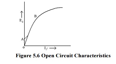
The O.C.C curve for self-excited generators whether shunt or series wound is shown in above Figure. Due to the residual magnetism in the poles, some emf (=OA) is generated even when If =0.Hence, the curve starts a little way up. The slight curvature at the lower end is due to magnetic inertia. It is seen that the first part of the curve is practically straight. This is due to fact that at low flux densities reluctance of iron path being negligible, total reluctance is given by the air gap reluctance which is constant. Hence, the flux and consequently, the generated emf is directly proportional to the exciting current. However, at high flux densities, where μ is small, iron path reluctance becomes appreciable and straight relation between E and If no longer holds good. In other words, after point B, saturation of pole starts. However, the initial slope of the curve is determined by air-gap width. O.C.C for higher speed would lie above this curve and for lower speed, would lie below it.
Separately-excited Generator Let we consider a separately-excited generator giving its rated no-load voltage of E0 for a certain constant field current. If there were no armature reaction and armature voltage drop, then this voltage would have remained constant as shown in Figure by the horizontal line 1. But when the generator is loaded, the voltage falls due to these two causes, there by giving slightly dropping characteristics. If we subtract from E0 the values of voltage drops due to armature reaction for different loads, then we get the value of E-the emf actually induced in the armature under load conditions. Curve 2 is plotted in this way and is known as the internal characteristic.
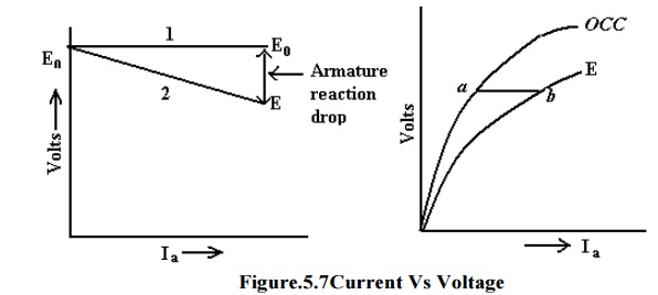
In this generator, because field windings are in series with the armature, they carry full armature current Ia. As Ia is increased, flux and hence generated emf is also increased as shown by the curve. Curve Oa is the O.C.C. The extra exciting current necessary to neutralize the weakening effect of armature reaction at full load is given by the horizontal distance ab. Hence, point b is on the internal characteristic.
6. External Characteristic (V/I)
It is also referred to as performance characteristic or sometimes voltage-regulating curve. It gives relation between the terminal voltage V and the load current I. This curve lies below the internal characteristic because it takes in to account the voltage drop over the armature circuit resistance. The values of V are obtained by subtracting IaRa from corresponding values of E. This characteristic is of great importance in judging the suitability of a generator for a particular purpose.It may be obtained in two ways
By making simultaneous measurements with a suitable voltmeter and an ammeter on a loaded generator or
Graphically from the O.C.C provided the armature and field resistances are known and also if the demagnetizing effect or the armature reaction is known.
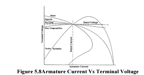
Figure above shows the external characteristic curves for generators with various types of excitation. If a generator, which is separately excited, is driven at constant speed and has a fixed field current, the output voltage will decrease with increased load current as shown. This decrease is due to the armature resistance and armature reaction effects. If the field flux remained constant, the generated voltage would tend to remain constant and the output voltage would be equal to the generated voltage minus the IR drop of the armature circuit. However, the demagnetizing component of armature reactions tends to decrease the flux, thus adding an additional factor, which decreases the output voltage.
Related Topics