Chapter: Mechanical : Manufacturing Technology : Metal Casting Process
Metal Casting Process
METAL CASTING PROCESS
PREREQUISTE DISCUSSION
Manufacturing
Manufacturing in its broadest sense is the process of converting raw materials into useful products.
• IT Includes
i) Design of the product
ii) Selection of raw materials and
iii) The sequence of processes through which the product will be manufactured. Casting.
Any Product in the engineering industry will be manufactured in the below methods
1. By totally deforming the metal to the required shape. (Casting /Forming)
1. By joining two metals. (Welding)
2. By removing the excess material from the raw stock.(Machining)
1Moulding
It is the process of preparing the cavity required for casting using the pattern (Physical Model), Moulding sand, Moulding boxes,(Cope, Drag, cheek) and other tools.
2Casting
Casting is the process of producing metal parts by pouring molten metal into the mould cavity of the required shape and allowing the metal to solidify. The solidified metal piece is called as "casting".
3Foundry
It is the place where both moulding and casting is done.
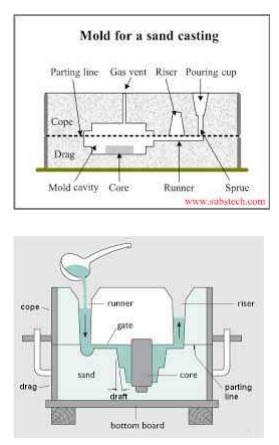
Sand Casting /Sand Moulding
Sand Casting is simply melting the metal and pouring it into a preformed cavity, called mold, allowing (the metal to solidify and then breaking up the mold to remove casting. In sand casting expandable molds are used. So for each casting operation you have to form a new mold.
Types of sand
a) Green-sand - mixture of sand, clay, and water,Binders (Molases, Linseed oil); "Green" means mold contains moisture at time of pouring.
b) Dry-sand - organic binders rather than clay and mold is baked to improve strength c) Skin-dried - drying mold cavity surface of a green-sand
- mold to a depth of u p t o 25 mm, using torches or heating d)Core Sand
e)Baking sand f)Loam Sand g)Parting sand, Etc.,
Patterns
Patterns are the replica or physical models of the final required shape of the casting, made by wood (teak,magony,pine), plastics, Metals, Plaster of paris etc.,
1Types of patterns
1.Solid pattern 2.Split piece pattern 3.Three piece pattern 4.Loose piece pattern 5.Match plate pattern 6.Segmental pattern 7.Sweep patten 8.skeleton Pattern 9.shell Pattern.
2Pattern Allowance.
Allowance are the extra dimensional compensation give to the pattern in order to attain the correct shape and size of the final solidified metal casting.Five types of allowances were taken into consideration for various reasons. They are
2.1.Shrinkage allowance
Any metal when heated to liquid stage and solidified will undergo change in dimension. Mostly the dimension of the product will be reduced, then the actual size of the pattern. Hence the patterns are made slightly in larger dimensions.(3%-5%)
2.2.Draft allowance
It will be difficult to remove the pattern from the mould cavity (without disturbing the mould) after ramming of sand. Hence the pattern (wooden or metal pattern) is slightly given 2 o– 3 o TAPER in the z - axis or vertical direction.
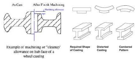
2.3. Finish allowance
It is otherwise called as machining allowance .The pattern is made slightly 5mm -10mm large in dimension than the required final part dimension. After casting the extra material is removed from the solidified material by machining.
2.4.Shake or Rapping allowance.
Before withdrawing the pattern it is rapped and thereby the size of the mould cavity increases. Actually by rapping , the external sections move outwards increasing the size and internal sections move inwards decreasing the size. This allowance is kept negative and hence the pattern is made slightly smaller in dimensions 05.1.0 mm.
2.5.Distortion allowance.
Some material might tend to bend or distort from the actual size or dimensions. Hence the pattern is give counter balance degree or angle of recess so that the material will be in the required dimension when solidified in the mould cavity.
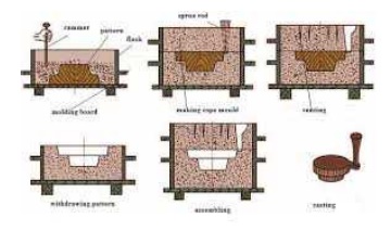
Steps in Sand Casting
The cavity in the sand mold is formed by packing sand around a pattern,
separating themold into two halves
• The mold must also contain gating and riser system
• For internal cavity, a core must be included in mold
• A new sand mold must be made for each part
1.Pour molten metal into sand mold
2. Allow metal to solidify
3. Break up the mold to remove casting
4. Clean and inspect casting
5. Heat treatment of casting is sometimes required to improve metallurgical properties.
FURNACES USED FOR MELTING METALS FOR CASTING
1 Types of furnace used in a casting industry.
–Crucible Furnace
– Electric-arc Furnace
– Induction Furnace --Reverbratory furnace
Blast Furnace
- Cupola Furnace.
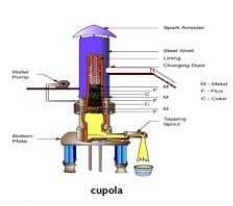
1.1.Cupola Furnace
• A continuous flow of iron emerges from the bottom of the furnace.
• Depending on the size of the furnace, the flow rate can be as high as 100 tones per hour.
.At the metal melts it is refined to some extent, which removes contaminants. This makes this process more suitable than electric furnaces for dirty charges.
SPECIAL CASTING PROCESS.
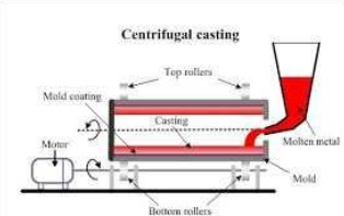
1.Centrifugal casting
Centrifugal casting uses a permanent mold that is rotated about its axis at a speed between300 to 3000 rpm as the molten metal is poured.Centrifugal forces cause the metal to be pushed out towards the mold walls, where it solidifies after cooling.Centrifugal casting has greater reliability than static castings. They are relatively free from gas and shrinkage porosity. Surface treatments such as case carburizing, flame hardening and have to be used when a wear resistant surface must be combined with a hard tough exterior surface.One such application is bimetallic pipe consisting of two separate concentric layers ofdifferent alloys/metals bonded together.
2. CARBON DI OXIDE PROCESS MOULDING.
Working Principle
The highly flowable mixture of pure dry silica sand and sodium silicate binder is rammed or blown into the mould or core box. Carbon –dioxide gas at a pressure of about 1.5 bar is diffused through the mixture (of sand and sodium silicate) to initiate the hardening reaction which takes from a few seconds to a few minutes depending upon the size of core or mould.Passage of carbon-dioxide through the sand containing sodium silicate produces carbonic acid in the aqueous solution, this causes a rise in the SiO2- Na2O ratio and the formation of a colloidal silica gel which hardens and forms a bond between the sand grains. The reaction is represented by the following equation.
NaSiO3 (Sodium Silicate) + CO2 -------à NaCO3 + SiO2 (Silica Gel)
Carbon Dioxide Moulding Operation
This sand is mixed with 3 to 5 % sodium silicate liquid base binder in Muller for 3 to 4 minutes. Additives such as coal powder, wood flour sea coal, and dextrin may be added to b improve its properties. Aluminium oxid e Kaolin clay may also added to the sand. Patterns use d in this method may be coated with Zinc of 0.05 mm to 0.13 mm and then spraying a layer of aluminium or brass of about 0.25 mm thickness for good surface finish and good results.
Advantages
• Operation is speedy since we can use the mould and cores imm ediately after processing.
• Heavy and rush orders
• Floor space requirement is less
• Semi skilled labor may be used.
Disadvantages
Difficult in reus ing the moulding sand.
Investment Casting
Investment casting produces very high surface quality and dim ensional accuracy. Investm ent casting is commonly used for precision equipment such as surgical e quipment, for complex geometries and for p recious metals.
This process is co mmonly used by artisans to produce highly detailed artwork. The first step is to produce a pattern or replica of the finished
mould. Wax is most commonly used to form the pattern, alth ough plastic is also used.
Patterns are typically mass-produced by injecting liquid or semi-liquid wax into a perm anent die.
Prototypes, small production runs and specialty projects can also be undertaken by carving wax models.
![]()
Cores are typica lly unnecessary but can be used for complex internal structures. Rapid prototyping techniques have been developed to produce expendable patter ns.
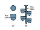
![]() Several replicas are often attached to a gating system constr ucted of the same material to form a tree assembly. In this way multipl e castings can be produced i n a single pouring.
Several replicas are often attached to a gating system constr ucted of the same material to form a tree assembly. In this way multipl e castings can be produced i n a single pouring.
Advantages
– Parts of great complexity and intricacy can be cast
– Close dimensional control and good surface finish
– Wax can usually be r ecovered for reuse
– Additional machining is not normally required - this is a net shape process
Disadvantages
– Many processing step s are required
– Relatively expensive process
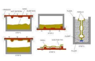
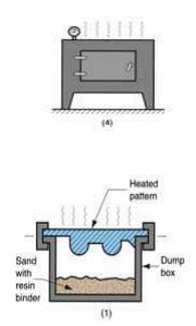
Shell-molding
Shell-mold casting yields better surface quality and tolerances.
The 2-piece pattern is made of metal (e.g. aluminum or steel), it is heated to between 175°C- 370° C, and coated with a lubricant, e.g. silico ne spray. Each heated half-pattern is covered with a mixture of sand and a thermoset resin/epoxy binder. The binder gl ues a layer of sand to the pattern, forming a shell. The process may be repeate d to get a thicker shell.The assembly is baked to cure it.The patterns are removed, and the two half-shells joined together to f orm the mold; metal is poured into th e mold. When the metal solidifies, the shell is broken to get the part.
Advantages of shell m oulding
Smoother cavity surface permits easier flow of molten meta l and better surface finish on casting
![]()
Good dimensiona l accuracy Machining often not required
Mold collapsibili ty usually avoids cracks in casting Can be mechaniz ed for mass production
Disadvantages of shell moulding.
More expensive metal pattern
Difficult to justif y for small quantities
Casting Defects
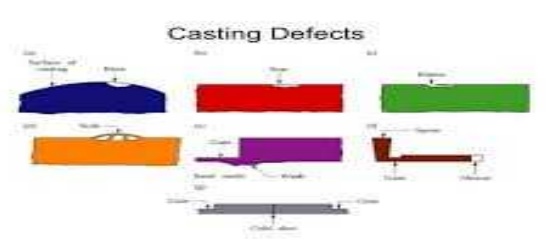
Casting defects
Defects may occur due to one or more of the following reasons:
– Fault in design of casting pattern
– Fault in design on mold and core
– Fault in design of gating system and riser
– Improper choice of moulding sand
– Improper metal composition
– Inadequate melting temperature and rate of pouring
Some common defects in castings:
a) Misruns b) Cold Shut c) Cold Shot d) Shrinkage Cavity e) Microporosity f) Hot Tearing
a)Misruns
It is a casting that has solidified before completely filling the mold cavity. Typical causes include
1) Fluidity of the molten metal is insufficient,
2) Pouring Temperature is too low,
3) Pouring is done too slowly and/or
4) Cross section of the mold cavity is too thin.
b) Cold Shut
A cold shut occurs when two portion of the metal flow together, but there is lack of
fusion between them due to premature freezing, Its causes are similar to those of a Misruns.
c) Cold Shots
When splattering occurs during pouring, solid globules of the metal are formed that
become entrapped in the casting. Poring procedures and gating system designs that avoid splattering can prevent these defects.
d) Shrinkage Cavity
This defects is a depression in the surface or an internal void in the casting caused by solidification shrinkage that restricts the amount of the molten metal available in the last region to freeze.
e) Microporosity
This refers to a network of a small voids distributed throughout the casting caused by
localized solidification shrinkage of the final molten metal in the dendritic structure. f) Hot Tearing
This defect, also called hot cracking, occurs when the casting is restrained or early stages
of cooling after solidification.
Non-destructive methods used for finding casting Defects.
The various casting defects may be on the surface, under the surface of the solidified casting. These defects are found out by the below mentioned non-Destructive Inspection methods.
1. Ultra Sonic Inspection
2. Liquid Penetrant Inspection
3. Magnetic Particle Inspection
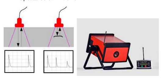
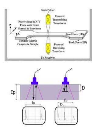
1.Ultra sonic Inspection.
Ultrasonic sound waves are in the frequency decibel which cannot be heared by a human ear. The bats use this kind of sound waves in-order to find the obstacles while flying. These waves will be reflected back to the source when obstructed. Similarly, in ultrasonic testing there is a probe which sends the ultrasonic sound waves into the metal part that is to be inspected. The sound waves will be reflected back after hitting the other end of the metal.
If there is a crack in the middle of the metal part, then the sound waves will be reflected before in advance.
This process is shown in the monitor as a graph. Thus the crack is identified and decided wheather to rectify the crack or reject the metal part.
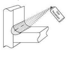
2. LPT (Liquid Penetrant Testing)
Chemicals Used.
1. Cleaner
2. Potassium Permanganate solution
3. Developer.
Initially the Casted Metal Part to be inspected is cleaned using Cleaner. Dust, oil, Grease etc are removed. Then potassium permanganate solution is sprayed over the surface of the metal part and allowed to remain for 5 – 7 mins. Then the potassium permanganate solution is cleaned.
Now developer is applied over the surface. Due to capillary action the rose/pink colour potassium permanganate liquid will reach the surface of the crack. And now the crack will be visible in pink/rose color.Thus the surface cracks are inspected on the casting.
ADVANTAGES & LIMITATIONS OF LPT
Cost of the chemicals is low when compared to UT & MPT.
Huge / Large size components can be inspected, only on the particular area, where it is required.
Time taken is less.
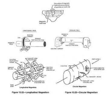
3.MPT Magnetic Particle testing.
This method of inspection is used on magnetic ferrous castings for detecting invisible
surface or slightly subsurface defects. Deeper subsurface defects are not satisfactorily detected because the influence of the distorted lines of magnetic flux (owing to a Discontinuity) on the magnetic particles spread over the casting.
The defects commonly revealed by magnetic particle inspection are quenching cracks, overlaps, thermal cracks, seams , laps, grinding cracks, fatigue cracks, hot tears Etc,
Working Principle.
When a piece of metal is place in a magnetic field and the lines of magnetic flux get intersected by a discontinuity such as a crack or slag inclusion in a casting, magnetic poles are induced on either side of the discontinuity. The discontinuity causes an abrupt change in the path of magnetic flux flowing through the casting normal to the discontinuity, resulting in a local flux leakage field and interference with the magnetic lines of force. This local flux disturbance can be detected by its effect upon magnetic particles which are attracted to the region of discontinuity and pile up and bridge over the discontinuity.
A surface crack is indicated (under favorable conditions) by a line of fine particles following the crack outline and a subsurface defect by a fuzzy collection of the magnetic particles on the surface near the discontinuity. Maximum sensitivity of indication is obtained when the discontinuity lies in a direction normal to the applied magnetic field and when the
Related Topics