Chapter: Civil : Railway Airport Harbour Engineering : Railway Engineering : Signalling and Interlocking
Mechanical Signalling System used in Railways
Mechanical Signalling System
The mechanical signalling system mostly involves signals and points as explained in this section.
1 Signals
The signals used in a mechanical signalling system are semaphore signals. These signals are operated by means of either a lower quadrant or an upper quadrant signalling system.
Lower quadrant signalling system
This system of signalling was designed so that the semaphore arm of the signal could be kept either horizontal or lowered. The lower left-hand quadrant of a circle is used for displaying a semaphore indication to the driver of a train. This concept was possibly developed based on the left-hand driving rules applicable on roads in the UK and in India.
Upper quadrant signalling system
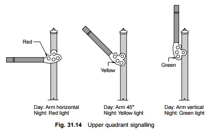
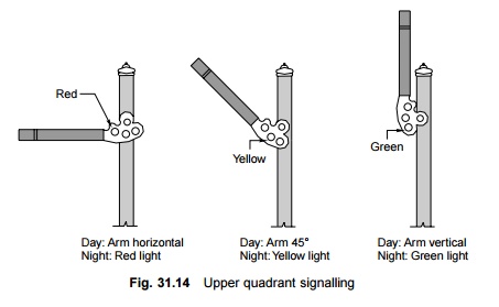
In lower quadrant signalling, the semaphore arm of the signal can only take two positions, namely, horizontal or lower; it is not possible to include a third position for the semaphore arm, such as vertically downward position, due to design as well as visibility problems, since as the semaphore arm would, in that case, be super imposed on the signal post. Due to this limitation, the upper quadrant system was developed, which can display more than two aspects. In this system, it is possible to incorporate three positions of the semaphore arm, namely, (a) horizontal,
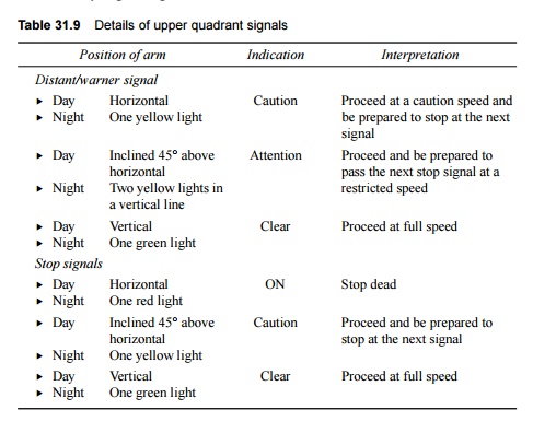
(b)inclined at an angle of about 45 o above the horizontal level, and (c) vertical, i.e., inclined at an angle of 90 o above the horizontal level. See Fig. 31.14. The positions of the arm, the corresponding indications, and their meanings are listed in Table 31.9.
2 Points
Points are set mechanically and are kept in locks and stretcher bars. The mechanical arrangement for operating them includes a solid rod with a diameter of 33 mm running from the lever provided in the cabin and connected to the point through cranks. Owing to transmission losses, the operating points with rods is restricted to a specified distance from the cabin.
Table 31.9 Details of upper quadrant signals
The following devices are used to ensure that the points are held rigidly in the last operated position under a moving train and to ensure absolute integrity of the same.
(a) Point locks to hold the point in the required position and to rigidly hold the point in the position of the last operation.
(b) Detectors to detect lock and switches.
(c) Lock bars to prevent the movement of points when a train is passing over
them.
These devices are further discussed in the subsequent paragraphs.
Point locks
A point lock is provided to ensure that each point is set correctly. It is provided between two tongue rails and near the toe of the switch assembly. The point lock consists of a plunger, which moves in a plunger casing. The plunger is worked by means of a plunger rod, which is connected to the signal cabin through a lock bar. Additionally, there are a set of stretcher blades and each blade is connected to one of the tongue rails. Each blade has two notches and they move inside the plunger casing along with the tongue rails. When the points are set correctly for a particular route, the notch in the stretcher blade rests in its proper position and the plunger rod enters the notch, locking the switch in the last operated position.
Detectors
Detectors are normally provided for all the points for the following reasons.
(a) To detect any defect or failure in the connection between the points and the lever as well as any obstruction between the stock and the tongue rail.
(b) To ensure that the correct signal, which corresponds to the point set, is lowered.
(c) A detector can be mechanical or electrical. In the case of a mechanical
detector, the point is held in the position of the last operation, which is achieved de facto by virtue of its design.
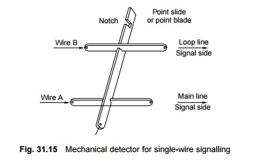
A detector normally consists of a detector box, which is provided with one slide for points and another set of slides for signals. The signal slides are perpendicular to the point slides. The slides are held suitably and no vertical movement of its same is possible. The signal slide has only one notch whereas the point slide has a number of notches depending upon the number of signals relevant to the points. The detector works on the principle that a particular signal can be lowered when the notch in that particular signal slide coincides with the notch in the point slide. For example, if the points are correctly set for the main line, the point slide moves and its notch comes to rest opposite the notch of the main line signal slide. The main line signal slide can then be pulled and the main line signal lowered. It may be noted here that the point slide will move and its notch will rest in its correct position only if the points are properly set and there is no obstruction in between.
The linear type (or slide type) of mechanical detector is used for single-wire signalling (Fig. 31.15), whereas the rotary type of detector (Fig. 31.16) is used for the double-wire signalling. A double-wheel detector is a rotary-type detector that rotates in a vertical plane. It detects the correct setting of points and, in addition, locks the points in the last operated position in the case of wire breakage.
Lock bar
A lock bar is provided to make it impossible to change the point when a train is passing over it. The lock bar is made of an angled section and its length is greater than that of the longest wheel base of a vehicle. Short revolving clips are provided to hold the lock bar in place on the inside face of one of the rails. The length of a lock bar is normally 12.8 m for BG and 12.2 m for MG sections.

The system is so designed that when the lever in the cabin is pulled to operate the locking device, the lock bar rises slightly above the rail level and then comes down. In the occurrence that a vehicle is positioned on the same location, the lock bar cannot rise above the rail level due to the flanges of the wheel and as such the point cannot be operated.
3 Different Transmission Systems
A signal is operated by pulling the associated lever and this action is transmitted through a single-wire or double-wire system. Initially, the single-wire system was the most popular way of operating signals and, in fact, some stations on Indian railways still use this system.
In the single-wire system, only one wire is stretched between the operating lever and the signal, whereas in the double-wire system a loop of two wires that run parallel to each other is wrapped over a drum lever and this system works on the principle of the pull and push arrangement.
Single-wire transmission
In the case of single-wire signalling, transmission is done with the help of the following equipment.
Lever frame A lever frame carries out the dual function of operating the single-wire system and actuating the interlocking in order to ensure safety. There are two types of lever frames, namely, a direct locking lever frame and a catch handle type lever frame, which are used for this purpose on the Indian Railways. The levers are pulled in order to operate the signals.
Signal transmission wire The entire transmission is done through an 8 or 10 SWG (standard wire gauge) galvanized steel wire. In places where the transmitting wire has to manoeuvre a turn, a multistandard galvanized steel wire is used, which is hauled over a horizontal or vertical wheel by pulling the lever. The arm of the signal remains as such while the lever is being pulled. When the lever returns to its normal position, the counterweight provided with the signal arm restores the wire back to its original position.
Cabin wire adjuster In order to accommodate the increase or decrease in the length of the cabin wire due to its expansion as a result of temperature variation, cabin wire adjusters are provided. If this is not done, it may result in inadequate lowering or drooping of the signal, thus giving rise to unsafe conditions.
Signal parts and fitting Signal parts and fittings are provided as per the details given in Fig. 31.2. The signal arm is brought to the 'off' position by a down rod. In the case of a breakdown of the signal transmission system, the signal arm is brought back to the horizontal position by means of a counterweight.
Limitations of single-wire signalling The single-wire signalling system does not give satisfactory performance in the operation of signals located at long distances. The signals do not operate correctly as they droop and do not get properly lowered, thereby endangering the trains. This defect develops due to the following reasons.
(a) Sagging of the wire due to its own weight.
(b) Expansion or contraction of the wire due to temperature variations.
(c) The elastic stretching of wires due to tension arising as a result of operating the lever.
(d) Entangling of the wire due to its slipping into the pulley stake and the horizontal and vertical wheels.
(e) Frequently breakage of the wire.
It has been noticed that the slightest slackness in attending to any one of these problems can cause the lowering of the signal, known as 'drooping', even when the lever is not pulled. On account of these defects, situations may arise in which a signal may not be lowered at all or a signal may not return to the 'on' position even after the lever has been restored to its normal position, if the wire gets entangled. As a result of these limitations, the single-wire signalling system can be used for operating signals from a range of only about 950 m.
Rod transmission In the single-wire transmission system, the signal is lowered or set in the 'off' position by pulling the lever. The signal returns to the 'on' position due to the effect of gravity as soon as the lever is restored to its normal position and the tension in the wire is released.
Where the operation of points is concerned, the points have to be set in either the normal or the reverse position; one of these positions can be attained through pulling and the other by pushing. Solid rods of 30 mm (1�" ) diameter are used to connect the levers to the points. The rods or pipes move on standard roller guides fixed at about 2-m (6-ft) intervals. A suitable crank is also used at every change of direction. The rods are subjected to expansion and contraction due to temperature variations.
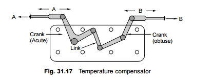
Rod temperature compensator A rod compensator, also known as a temperature compensator, is provided to neutralize the effect of thermal. It consists of a pair of cranks, one acute and one obtuse, connected by a link and is so designed that it absorbs the expansion or contraction due to temperature variations. The compensator is normally placed at the centre of the rod up to a length of 36.5 m. If more than one compensator is required, these are placed at quarter points.
As can be seen in Fig. 31.17, the points, A or B may move left or right, but the total distance between them remains the same.
Double-wire transmission system
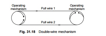
In this system, power is transmitted with the help of two wires from the lever to operated units such as signals, points, locks, detectors, etc. Each wire consists of 8 to 10 SWG solid galvanized steel wires attached to pulley stakes, which are driven firmly into the ground. The two wires are connected between the lever and the signal to form a continuous loop. When the lever is operated, it leads to the wire getting pulled and when the lever is brought back to its normal position, it results in a push to the wire. This pull and push mechanism (Fig. 31.18) causes the drum to rotate in one direction when the lever is pulled and in the other direction when it is restored to its normal position. The rotary motion of the drum is then converted into linear movement by the use of cams and cranks and this finally actuates the signal, as illustrated in Fig. 31.19, which shows the complete double-wire transmission system.
Advantages of double-wire transmission The main advantages of double-wire transmission over single-wire transmission are enumerated here.
(a) Operating a double-wire transmission system is easier.
(b) A double-wire transmission system permits multi-aspect signalling.
(c) The range of operations of the double-wire transmission system is greater.
(d) There is no drooping of signals in double-wire transmission. This results in better safety.
(e) The operating cost of a double-wire transmission system is less.
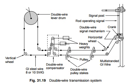
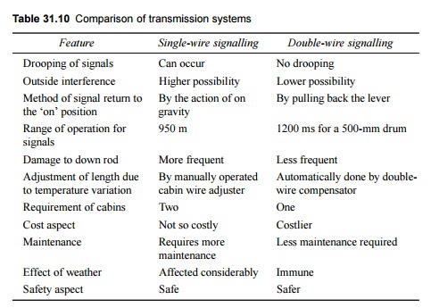
Table 31.10 compares a signal-wire and a double-wire signalling system. The special features of a double-wire signalling system are as follows.
Table 31.10 Comparison of transmission systems
(a) Double wire compensators are provided to perform the following functions.
(i) To maintain constant tension in the transmission system by adjusting the changes in length caused by temperature variations.
(ii) To provide protection against wire breakage. Whenever a wire breaks, the following compensator ensures that the signal is brought to the 'safe' position.
(b) Jockey weights are added to the main compensator weight to cater to a greater operating force.
(c) Coupling devices are provided to detect the couplings of two levers in a common transmission.
(d) Double-wire detectors are provided to detect the correct setting of the points and locks.
4 Operating Mechanism
In mechanical signalling, the signals and points are operated mechanically. The operation of these units, therefore, requires sufficient amount of power. To facilitate the quick and smooth operation of these equipment, levers are used in single-wire as well as in double-wire mechanical transmission. These levers may be installed individually near an operated unit such as a point or a signal or may be grouped together in a lever frame depending upon the type and standard of signalling. Lever frames may be of the following types.
Single-wire lever frame
In this type of lever frame, the lever is a bar fulcrumed on a shaft. The longer end of the bar rests towards the lever while the shorter end rests towards the signal or the point in order to gain mechanical advantage. Pulling the lever results in a movement of 200 mm in the case of points and 300 mm in the case of signal operation. All the levers that are required to operate different units such as points and signals are grouped together on a common fulcrum shaft in a compact lever frame, which is kept below the level of the operation platform. Only a convenient length of the lever is allowed to protrude beyond the platform to facilitate easy operation. A latch arrangement is also provided with the lever arm to maintain the lever in the position in which it was last operated.
Double-wire lever frames
Unlike single-wire systems, a double-wire transmission system is in the form of a loop, one end of which is wrapped across a drum that is provided with an arm. When this arm is rotated about the centre of the drum, it imparts a stroke of 550 mm or 600 mm depending upon the type of lever used. There are six types of double-wire levers used on Indian Railways that impart strokes of 500 mm to 600 mm.
When referring to points, normally a 500-mm stroke drum is capable of operating all the equipment satisfactorily up to a distance of 500 m. In the case of any difficulty, 600-mm stroke levers may be used.
The interlocking of these operating mechanisms is discussed in Section 31.9.
5 Monitoring Units
Monitoring units are provided to ensure that points are set properly and locked for the safe passage of trains. These units are also sometimes used to monitor the passage of trains. Detectors and treadles are used as monitoring devices on Indian Railway. Detectors have been discussed in Section 31.6.2.
Treadle for monitoring passage of train
It is not always possible for a train to pass immediately after the route has been set for its reception or departure and the signals have been placed in the 'off' position. There is generally a time gap between these two events. During this intervening period, the operator has to conduct many other operations in the yard such as the shunting of some other train, monitoring the movement of other trains, and booking tickets, and in the process, the operator is likely to forget about the passage of the train on the route set by him. In order to eliminate human error, some devices are provided to monitor the presence or passage of a train over a defined portion of the track. Most of these devices are either electrical or electronic. However, the basic electro-mechanical device used for monitoring the passage of a train is a treadle. A treadle unit is fastened with the rails. The passage of the train deflects the point of contact, which is transmitted to the cabin thereby proving and confirming the passage of the train.
Related Topics