Chapter: civil : Applied Hydraulic Engineering: Turbines
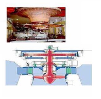
Kaplan turbine
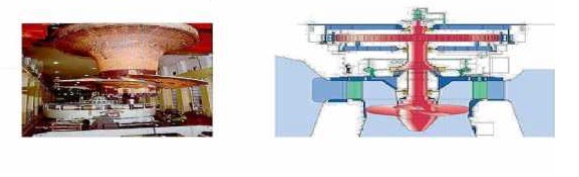
Kaplan turbine
The Kaplan turbine is a propeller-type
water turbine which has adjustable blades. It was developed in 1913 by the
Austrian professor Viktor Kaplan, who combined automatically - adjusted
propeller blades with automatically-adjusted wicket gates to achieve efficiency
over a wide range of flow and water level.
The Kaplan turbine was an evolution of
the Francis turbine. Its invention allowed efficient power production in low-
head applications that was not possible with Francis turbines.
![]()
Kaplan turbines are now widely used
throughout the world in high-flow, low-head power production. The Kaplan
turbine is an inward flow reaction turbine, which means that the working fluid
changes pressure as it moves through the turbine and gives up its energy. The
design combines radial and axial features.
The
inlet is a scroll-shaped tube that wraps around the turbine's wicket gate.
Water is directed tangentially through the wicket gate and spirals on to a
propeller shaped runner, causing it to The outlet is a specially shaped draft
tube that helps decelerate the water and recover kinetic energy.
The
turbine does not need to be at the lowest point of water flow as long as the
draft tube remains full SCEofwater. A higher the draft tube. The resulting
pressure drop may lead to cavitation.
Variable geometry of the wicket gate and
turbine blades allow efficient operation f or a range of flow conditions.
Kaplan turbine efficie ncies are typically over 90%, but may be lower i n very
low head applications.
Current
areas of research include CFD driven efficiency improvements and new de signs
that raise survival rates of fish passin g through.
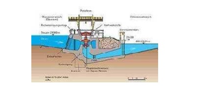
1.Applications
Kaplan
turbines are widely used throughout the world for electrical power prod uction.
They cover the lowest head hydro sites and are especially suited for high flow
conditions. Inexpensive micro turbines are manufactured for individual power
production with as little as two feet of head.Kaplan turbine is low head
turbine. Large Kaplan turbines are individually designed for each site to
operate at th e highest possible efficiency, typically over 90%. They are very
expensive to design, manufacture and install, but operate for decades.
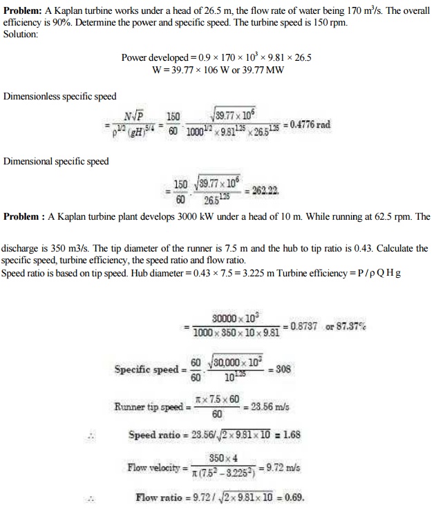
Problem: A Kaplan turbine works under a
head of 26.5 m, the flow rate of water being 1 70 m3/s. The overall
efficiency is 90%. Determine the po wer and specific speed. The turbine
speed is 150 rpm.
Solution:
Power
developed = 0.9 � 170 � 10 3 � 9.81 � 26.5
W = 39.77
� 106 W or 39.77 MW
Dimensionless
specific speed
Problem : A Kaplan turbine plant d evelops
3000 kW under a head of 10 m. While runni ng at 62.5 rpm. The discharge is 350
m3/s. The tip diameter of the runner is 7.5 m and the hub to tip ratio is 0.43.
Calculate the specific speed, turbine efficiency, the speed ratio and flow
ratio.
Speed
ratio is based on tip speed. Hub diameter = 0.43 � 7.5 = 3.225 m Turbine
efficiency = P / ? Q H g
2 Variations
The
Kaplan turbine is the most widely used of the propeller-type turbines, but
several other variations
exist:
Propeller Turbines have non-adjustable propeller vanes. They
are used in where the range ofhead is
not large. Commercial products exist for producing several
hundred watts from only a few feet of head. Larger propeller turbines produce
more than 100 MW.
2.2 Bulb or Tubular turbines
Bulb or Tubular turbines are designed into the
water delivery tube. A large bulb is centered inthe water pipe which holds the
generator, wicket gate and runner. Tubular turbines are a fully axial design,
whereas Kaplan turbines have a radial wicket gate.
2.3 Pit turbines
Pit turbines are bulb turbines
with a gear box. This allows for a smaller generator and bulb. Straflo turbines
are axial turbines with the generator outside of the water channel, con nected
tothe periphery of the runner.
2.4 S- turbines
S-
turbines eliminate the need for a bulb housing by placing the generator outside
of the waterchannel. This is accomplished with a jog in the water channel and a
shaft connecting the runner and generator.
2.5
Tyson turbines
Tyson turbines are a
fixed propeller turbine designed to be immersed
in a fast flowing river,either permanently
anchored in the river bed, or attached to a boat or barge.
Related Topics