Chapter: Automation, Production Systems, and Computer Integrated Manufacturing : Flexible Manufacturing Systems
Flexible Manufacturing Systems(FMS) Components
FMS
COMPONENTS
As
indicated in Out definition. there are several basic components of an FMS: (1)
workstations, (2) material handling and storage system, and (3) computer
control system. In addition, even though an FMS is highly automated, (4) people
are required to manage and operate the system. We discuss these four FMS
components in this section.

Workstations
The
processing or assembly equipment used in an FMS depends on the type of work
accomplished by the
system. In a system designed for machining operations, the principle types of
processing station are CNC machine tools. However, the FMS concept is also applicable
to various other processes as well. Following are the types of workstations
typically found in an FMS.
Load/Unload Stations. The
load/unload station is the physical interface between the FMS and the rest of the factory. Raw work-parts enter the system
at this point, and finished parts exit the system from here. Loading and
unloading can be accomplished either manually or by automated handling systems. Manual loading and unloading is prevalent
in most FMSs today. The load/unload station should be ergonomically designed to
permit convenient and safe movement of work parts. For parts that are too heavy
to lift by the operator, mechanized cranes and other handling devices are
installed to assist the operator.
A
certain level of cleanliness must be maintained at the workplace. and air
hoses or other washing facilities are
often required to flush away chips and ensure clean mounting and locating
points. The station is often raised slightly above floor level using an open-grid
platform to permit chips and cutting fluid to drop through the openings for
subsequent recycling or disposal
The
load/unload station should include a data entry unit and monitor for
communication between the operator and the computer system. Instructions must
be given to the operator regarding which part to load onto the next pallet to
adhere to the production schedule. In cases when different pallets are required
for different parts, the correct pallet must be supplied to the station. In
cases where modular fixturing is used, the correct fixture must be specified.
and the required components and tools must be available at the workstation to
build it. 'When the part loading procedure has been completed. the handling
system must proceed to launch the pallet into the system; however, the handling
system must be prevented from moving the pallet while the operator is still
working. All of these circumstances require communication between the computer
system and the operator at the load/unload station
Machining Stations. The most
common applications of FMSs arc machining operations, The workstations used in
these systems are therefore predominantly CNC machine tools. Most common is the
CNC
machining center (Section 14.3.3): in particular.
the horizontal rnachining center. CNC machining centers possess features that
make them compatible with the FMS, including automatic tool changing and tool
storage, use of palletized work-parts, CNC, and
capacity for distributed numerical control (DNC) (Section 6.3). Machining
centers can be ordered with automatic pallet changers that can be readily
interfaced with the FMS part handling system. Machining centers are generally
used for non-rotational parts. For rotational parts, turning centers are used; and for parts that are mostly rotational
hut require multi-tooth rotational cutters (milling and drilling), mi11·turn centers can be used.
In some
machining systems, the types of operations performed are concentrated in a
certain category, such as milling or turning. For milling, special milling machine modules can be used to
achieve higher production levels than a machining center is capable of. The
milling module can be vertical spindle, horizontal spindle, or multiple
spindle. For turning operations. Special turning modules can be designed for the FMS, In conventional turning, the
work-piece IS rotated against a tool that is held in the machine and fed in a
direction parallel to the axis of work rotation. Parts made on most FMSs are
usually non-rotational: however, they may require some turning in their process
sequence. For these cases, the parts are held in a pallet fixture throughout
processing on the FMS, and a turning module is designed to rotate the single
point tool around the work.
Other Processing Stations.
The FMS concept has been applied to other processing operations in addition to
machining. One such application is sheet metal fabrication processes. The
processing workstations consist of press-working operations, such as punching, shearing,
and certain bending and forming processes. Also, flexible systems are being
developed to automate the forging process. Forging is traditionally a very
labor-intensive operation. The workstations in the system consist principally
of a heating furnace, a forging press. and a trimming station.
Assembly. Some FMSs
are designed to perform assembly operations. Flexible automated
assembly systems are being developed to replace manual labor in the assembly of
products typically made in batches. Industrial robots are often used as the
automated workstations in these flexible assembly systems. They can be
programmed to perform tasks with variations in sequence and motion pattern to
accommodate the different product styles assembled in the system. Other examples
of flexible assembly workstations are the programmable component placement
machines widely used in electronics assembly.
Other Stations and Equipment. Inspection
can be incorporated into an FMS, cither by including, an inspection operation
at a processing workstation or by including a station specifically designed for
inspection. Coordinate measuring machines (Section 23.4), special inspection
probes that can be used in a machine tool spindle (Section 23.4.b), and machine vision (Section 23.0) are three possible
technologies for performing inspection on an FMS. Inspection has been found to
be particularly important in flexible assembly systems to ensure that
components have been properly added at the workstations. We examine the topic of automated inspection in more
detail in Chapter 22 (Section 22.3).
In
addition to the above, other operations and functions are often accomplished on
an FMS. These include stations for cleaning parts and/or pallet fixtures.
central coolant de
livery
systems for the entire FMS, and centralized chip removal systems often
installed below floor level
Material
Handling and Storage System
The
second major component of an FMS is its material handling and storage system.
In this subsection, we discuss the functions of the handling system, material
handling equipment typically used in an FMS, and types of FMS layout.
Functions
of the Handling System. The material handling and storage system in an FMS
performs the fol1owing functions:
Random, independent
movement of work-parts between stations. This means that parts must be capable of moving from
anyone machine in the system to any other machine. to provide various
routing alternatives for the different parts and to make machine substitutions
when certain stations are busy.
Handle a
variety of work-part configurations. For prismatic parts, this is
usually accomplished by using modular pallet fixtures in the handling system.
The fixture is located on the top face of the pallet and is designed to
accommodate different part configurations by means of common components, quick change
features, and other devices that permit a rapid buildup of the fixture for a
given part. The base of the pallet is designed for the material handling
system. For rotational parts, industrial robots are often used to load and
unload the turning machines and to move parts between stations.
Temporary
storage. The number of parts in the FMS will typically exceed the number of parts
actually being processed at any moment. Thus, each station has a small queue of
parts waiting to be processed. which helps to increase machine utilization.
Convenient
access for loading and unloading work-parts. The handling system must include locations for load/unload stations.
Compatible with computer control. The
handling system must be capable of being controlled
directly by the computer system to direct it to the various workstations,
load/unload stations, and storage areas
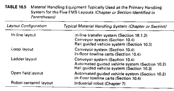
Material
Handling Equipment. The types of material handling systems used to transfer
parts between stations in an F.\1S include a variety of conventional material
transport equipment (Chapter 10), inline transfer mechanisms (Section
18.1.2),and industrial robots (Charter 7) The material handling function in an
FMS is often shared between two systems: (1) a primary handling system and (2)
a secondary handling system. The primary handling system establishes the basic layout of the FMS and is
responsible for moving work-parts
between stations in the system. The types of material handling equipment
typically utilized for FMS layouts are summarized in Table 16.5
The secondary handling system consists of
transfer devices, automatic pallet changers. and similar mechanisms located at
the workstations in the FMS. The function of the secondary handling system is
to transfer work from the primary system to the machine tool or other
processing station and to position the parts with sufficient accuracy and
repeatability to perform the processing or assembly operation. Other purposes
served by the secondary handling system include: (1) reorientation of the work-part
if necessary to present the surface that is to be processed and (2) buffer
storage of parts to minimize work change time and maximize station utilization.
In some FMS installations, the positioning and requirements at the individual
workstations are satisfied by the primary work handling system. In these cases,
the secondary handling system is not included,
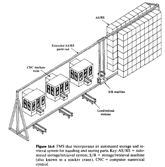
The
primary handling system is sometimes supported by an automated storage system
(Section: 1.4). An example of storage in an FMS is illustrated in Figure 16.6.
The FMS is integrated with an automated storage/retrieval system (AS/RS), and
the S/R machine serves the work handling function for the workstations as well
as delivering parts to and from the storage racks,
FMS
Layout Configurations. The material handling system establishes the FMS layout.
Most layout configurations found in today's FMSs can he divided into five
categories: (1) inline layout, (2) loop hl)'OU1, (3) ladder layout. (4) open
field layout, and (5) robot-centered cell.
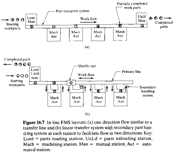
In the inline layout, the machines and handling
system are arranged in a straight line, as illustrated in Figure, 16.6 and
16.7. In its simplest form. the parts progress from one workstation to the next
in a well defined sequence, with work always moving in one direction and no
back flow, as in Figure 16.7(a). The operation of this type of system is similar
to a transfer lin., (Chapter 18). except that a variety of work-parts are
processed in the
TABLE 16.5
Material Handling Equipment Typically Used as the Primary Handling System
for the Five FMS Layouts (Chapter or Section Identified in
system.
Since all work units follow the same routing sequence, even though the
processing varies at each station, this system is classified as type III A in
our manufacturing systems classification system. For inline systems requiring
greater routing flexibility, a linear transfer system that permits movement in
two directions can be installed. One possible arrangement for doing this is
shown in Figure 16.7(b), in which a secondary work handling system is provided
at each workstation to separate most of the parts from the primary line. Because
of the variations in routings, this is II
type II A manufacturing system.
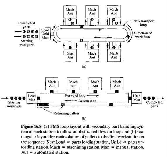
In the loop layout, the workstations are
organized in a loop that is served by II part
handling system in the same shape, as shown in Figure 16.8(a). Parts usually
flow in one direction around the loop, with the capability to stop and be
transferred to any station. A secondary
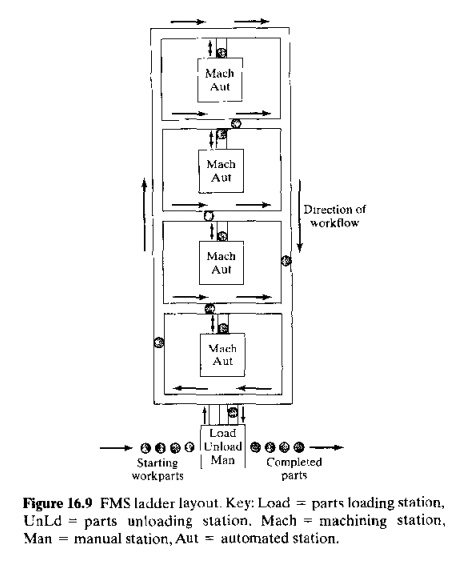
The ladder layout consists of a loop with
rungs between the straight sections of the loop, on which workstations are
located, as shown in Figure 16.9.The rungs increase the possible ways of
getting from one machine to the next, and obviate the need for a secondary
handling system. This reduces average travel distance and minimizes congestion
in the handling system, thereby reducing transport time between workstations.
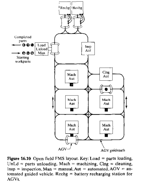
The open field layout consists of multiple
loops and ladders and may include sidings as well. as illustrated in Figure
16.m This layout type is generally appropriate for processing a large family of
parts. The number of different machine types may be limited, and parts are
routed to different workstations depending on which one becomes available
first.
The robot-centered cell (Figure 16.1) uses
one or more robots as the material handling system. Industrial robots can be
equipped with grippers that make them well suited for the handling of
rotational parts, and robot centered FMS layouts are often used to process
cylindrical or disk shaped parts
Computer
Control System
The FMS
includes a distributed computer system that is interfaced to the workstations,
material handling system, and other hardware components. A typical FMS computer
system consists of a central computer and microcomputers controlling the
individual machines and other components. The central computer coordinates the
activities of the components to achieve smooth overall operation of the system.
Functions performed by the FMS computer control system can be grouped into the
following categories:
Workstation
control. In a fully automated FMS, the individual processing or assembly stations
generally operate under some form of computer control. For a machining system,
CNC is used to control the individual machine tools.
Distribution of control instructions to
workstations. Some form of central intelligence is also required
to coordinate the processing at individual stations. In a machining FMS, part
programs must be downloaded to machines, and DNC is used for this purpose, The
DNC system stores the programs, allows submission of new programs and editing
of existing programs as needed, and performs other DNC functions (Section 6.3).
Production
control. The part mix and rate at which the various parts are launched into the system must be managed. Input data
required for production control includes desired daily production rates per
part. numbers of raw work-parts available, and number of applicable pallets.'
The production control function is accomplished by routing an applicable pallet
10 the load/unload area and providing instructions to the operator for loading
the desired work-part.
Traffic
control. This refers to the management of the primary material handling system
that moves workparts between stations. Traffic control is accomplished by
actuating switches at branches and merging points. stopping parts at machine
tool transfer locations, and moving pallets to load/unload stations.
Shuttle
control. This control function is concerned with the operation and control of the secondary handling system at each
workstation. Each shuttle must be coordinated with the primary handling system
and synchronized with the operation of the machine tool it serves,
Work-piece
monitoring. The
computer must monitor the status of each cart and/or pallet in the primary and secondary handling systems as well as
the status of each of the various workpiece types.
Tool
control. In a machining system, cutting tools are required. Tool control is
concerned with managing two aspects of the cutting tools:
Tool location. This involves keeping track of
the cutting tools at each workstation, If one or mere tools required to process
a particular workpiece is not present at the station that is specified in the
part's routing, the tool control subsystem takes one or both of the following
actions: (a) determines whether an alternative workstation that has the
required tool is available and/or (b) notifies the opera tor responsible for
tooling in the system that the tool storage unit at the station must be loaded
with the required cutter(s).
Tool life monitoring. 1.nthis
aspect of tool control, a tool life isspecif.ied to the computer for each cutting tool in the FMS. A record of the
machining time usage i••maintained for each of the tools, and when the
cumulative machining time reaches the specified life of the tool, the operator
is notified that a tool replacement is needed.
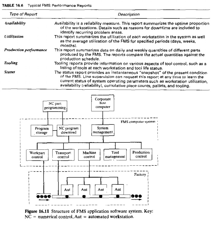
K Performance monitoring and reporting.
The computer control system is programmed
to collect data on the operation and performance of the FMS. This data is
periodically summarized, and reports are prepared for management on system
performance. Some of the important reports that indicate FMS performance are
listed in Table 16.6
Diagnostics. This function is available to a
greater or lesser degree on many manufacturing systems to indicate the probable
source of the problem when a malfunction occurs. It can also be used to plan
preventive maintenance iu the system and to identify Impending failures. The
purpose of the diagnostics function is to reduce breakdowns and downtime and
increase availability of the system.
The
modular structure of the FMS application software for system control is
illustrated in Figure 16.11. It should be noted that an FMS possesses the characteristic
architecture or a DNC system. As in other DNC systems. Two-way communication is
used. Data and commands an: sent from the central computer to the individual
machines and other hardware components, and data on execution and performance
are transmitted from the components hack up to the central computer. In
addition, an uplink from the FMS to the corporate host computer is provided
Human Resources
One
additional component in the FMS is human labor. Humans are needed to manage the
operations of the FMS. Functions typically performed by humans include: (1) loading raw
workparts into the system, (2) unloading finished parts (or assemblies) from
the system.
(3)
changing and setting tools. (4) equipment maintenance and repair, (5) NC part
programming in a machining system, (6) programming and operating the computer
system, and (7) overall management of the system
Related Topics