Chapter: Civil : Highway Planning and Alignment : Design Of Flexible And Rigid Pavements
Equivalent single axle load
Equivalent
single axle load
Vehicles can have many axles which will distribute
the load into different axles, and in turn to the pavement through the wheels.
A standard truck has two axles, front axle with two wheels and rear axle with
four wheels. But to carry large loads multiple axles are provided. Since the
design of flexible pavements is by layered theory, only the wheels on one side
needed to be considered. On the other hand, the design of rigid pavement is by
plate theory and hence the wheel load on both sides of axle need to be
considered. Legal axle load: The maximum allowed axle load on the roads is
called legal axle load. For highways the maximum legal axle load in India,
specified by IRC, is 10 tonnes. Standard axle load: It is a single axle load
with dual wheel carrying 80 KN load and the design of pavement is based on the
standard axle load.
Repetition of axle loads: The deformation of
pavement due to a single application of axle load may be small but due to
repeated application of load there would be accumulation of unrecovered or
permanent deformation which results in failure of pavement. If the pavement
structure fails with N1 number of repetition of load W1
and for the same failure criteria if it requires N2 number of
repetition of load W2 , then W1 N1 and W2N2
are considered equivalent. Note that, W1N1 and W2
N2 equivalency depends on the failure criterion employed.
Equivalent
axle load factor: An equivalent axle load factor (EALF) defines the damage per
pass to a pavement by the ith type of axle relative to the damage
per pass of a standard axle load. While finding the EALF, the failure criterion
is important. Two types of failure criterias are commonly tigue cracking model
has the following form:
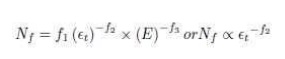
where, Nf
is the number of load repetition for a certain percentage of cracking, t
is the tensile strain at the bottom of the binder course, E is the modulus of
elasticity, and f1; f2; f3 are constants. If
we consider fatigue
Related Topics