Chapter: Civil : Design of Reinforced Concrete Elements : Limit State Design For Bond, Anchorage Shear and Torsion
Equilibrium Torsion And Compatibility Torsion
DESIGN FOR TORSION
INTRODUCTION
Torsion when
encountered in reinforced concrete members usually occurs in combination with
flexure shear. Torsion in its associated�pure?with metalformshafts)
is(generallyrarelyencounteredinreinforced concrete.
The interactive
behavior of torsion with bending moment and flexural shear in reinforced
concrete beams is fairly complex, owing to the no homogeneous, nonlinear and
composite nature of the material and the presence of cracks. For convenience in
design, codes prescribe highly simplified design procedures, which reflect a
judicious blend of theoretical considerations and experimental results.
These design procedures
and their bases are described in this chapter, following a brief review of the
general behavior of reinforced concrete beams under torsion.
EQUILIBRIUM
TORSION AND COMPATIBILITY TORSION
Torsion may be induced in a reinforced concrete member in various ways during the process of load transfer in a structural system. In reinforced concrete desi commonly used to refer to two different torsion -inducing situations.
In �equilibrium torsion?,ducedbyaneccentric
loading,the and torsion equilibrium conditions is alone insuffice
in determining the
twisting moments. In �compati angle of twist and the resulting twisting moment
depends on the torsional stiffness of the member.
In some (relatively rare) situations, axial force
(tension or compression) may also be involved.
It must be clearly
understood that this is merely a matter of terminology, and that it does not
imply for instance, equilibrium conditions need not be satisfied in cases of
There are some
situations (such as circular beams supported on multiple columns) where both
equilibrium torsion and compatibility torsion coexist.
EQUILIBRIUM TORSION
This
is associated with twisting moments that are developed in a structural member
is maintain static equilibrium with the external loads, and are independent of
the torsional stiffness of the member. Such torsion must be necessarily
considered design. The magnitude of the twisting moment does not depend on the
torsional stiffness of the member, and is entirely determinable from statics
alone. The member has to be designed for the full torsion, which is transmitted
by the member to the supports. More ever, the end(s) of the member should be suitably
restrained to enable the member to resist effectively the torsion induced.
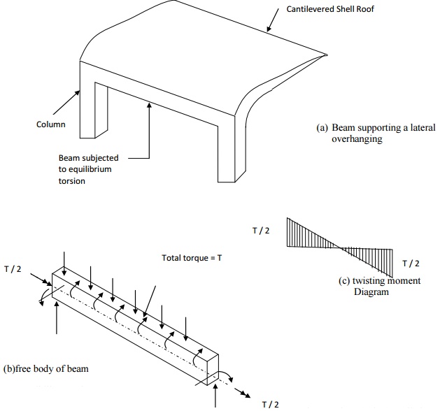
Typically, equilibrium torsion is induced in beams supporting lateral over
hanging projections, and is caused by the eccentricity in the loading (Figure).
Such torsion is also induced in beams curved plan and subjected to gravity
loads, and in beams where the transverse loads are eccentric with respect to
the shear centre of the cross -section.

Compatibility
Torsion
This
is the name given to the type of torsion induced in a member rotations (twists)
applied at one or more points along the length of the member. It twisting
moments induced are directly dependent on the torsional stiffness of the
member. These moments are generally statically in determine and their analysis
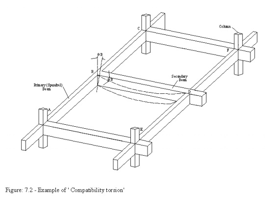
necessarily involves (rotational) compatibility in the floor beam system has
shown in figure,Bat th the end B. As the primary (Spandrel) beam ABC is
monolithically connected with the secondary beam BD at the joint B.,
compatibilityB inatthespandrelBimpliesbeamABC,and a bendinganangl moment will
develop at the end b of beam BD. The bending moment will be equal to, and will
act in a direction opposite to the twisting moment, in orderBandthetwistingto/
sat bending moment at b depends on the torsional stiffness of beam ABC and the
flexural stiffness of beam BD.
The torsional stiffness of a reinforced concrete member is drastically reduced by torsional cracking. This results in a very large increase in the angle of twist, induced twisting moment. For this reasons, the code (CL.40.1) permits the designer to neglect the torsional stiffness of reinforced concrete members at the structural analysis stage itself, so that the need for detailed design for torsion in such cases does not arise at the design stage. With reference to figure, this implies assuming a fictitious hinge (i.e., no rotational restraint) at the end B of the beam BD, and assuming a continuous support (spring, support, actually)at the joint D. Incidentally, this assumption helps in reducing the degree of static indeterminacy of the structure (typically, a grid floor), thereby simplifying the problem of structural analysis. Thus, the code states:
In general, where the
torsional resistance or stiffness of members has not been taken into account in
the analysis of a structure no specific calculations for torsion will be
necessary [CL40.1 of the code].
Of course, this
simplification implies the acceptance of cracking and increased deformations in
the torsional member. It also means that during the first time loading, a
twisting moment up to the cracking torque of the the member, prior to torsional
cracking. In order to control the subsequent cracking and to impart ductility
to the member, it is desirable to provide a minimum torsional reinforcement,
equal to that required to resist the �cracking t reinforcement specified by the code (CL. 25.5.1.6) is to ensure some degree of control of torsional cracking of beams due to compatibility torsion.
If, however, the designer chooses to consider � that
a realistic estimate of torsional stiffness is made for the purpose of
structural analysis, and the required
torsional
reinforcement should be provided for the calculated twisting moment.
Related Topics