Chapter: 9th Science : Electric charge and electric current
Electric circuit diagram
Electric circuit diagram
To represent an
electrical wiring or solve problem involving electric circuits, the circuit
diagrams are made.
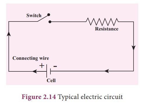
The four main components
of any circuits namely the, (i) cell, (ii) connecting wire, (iii) switch and
(iv) resistor or load are given above. In addition to the above many other
electrical components are also used in an actual circuit. A uniform system of
symbols has been evolved to describe them. It is like learning a sign language,
but useful in understanding circuit diagrams.
1. Some common symbols in the electrical circuit
Some of the symbols are
shown in Table 1.

2. Different electrical circuits
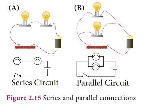
Look at the two
circuits, shown in Figure 2.15. In Figure A two bulbs are connected in series
and in Figure B they are connected in parallel. Let us look at each of these
separately.
Series circuits
Let us first look at the
current in a series circuit. In a series circuit the components are connected
one after another in a single loop. In a series circuit there is only one
pathway through which the electric charge flow. From the above we can know that
the current I all along the series circuit remain same. That is in a series
circuit the current in each point of the circuit is same.
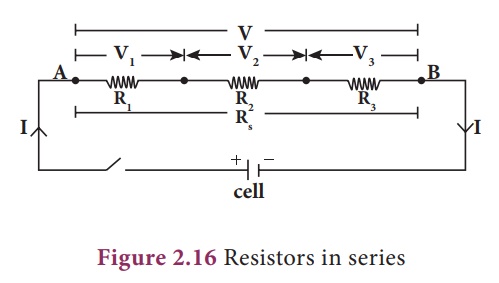
Now, for example, let us
consider three resistors of resistances R1, R2 and R3
that are connected in series. When resistors are connected in series, same
current is flowing through each resistor as they are in a single loop. If the
potential difference applied between the ends of the combination of resistors
is V, then the potential differences across each resistor R1, R2
and R3 are V1, V2 and V3
respectively as shown in Figure 2.16.
The net potential
difference, V = V1 + V2 + V3
By Ohm’s law, V1
= IxR1; V2 = IxR2; V3 = IxR3;
and V = IxRS
where R3 is
the equivalent or effective resistance of the series combination.
Hence, (IxRs)
=(IxR1)+ (IxR2) + (IxR3) = Ix(R1 +
R2 + R3)
RS = R1
+ R2 + R3
Thus, the equivalent
resistance of a number of resistors in series connection is equal to the sum of
the resistance of individual resistors.
Suppose, n resistors are
connected in series, then the equivalent resistor is,
RS = R1
+ R2 + R3 + . . . . . . + Rn
Exercise 2.7
Look at the series
circuit below.
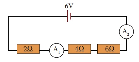
a. What is the effective resistance of the three resistors?
b. What is the current measured by ammeter A1 and
ammeter A2?
c. What is the potential difference across each resister?
Solution:
a) Effective resistance
R 5 R1 1 R2 1 R3
= 2 + 4 1 6 = 12V
b) Since, V= 6 V and effective resistance is 12V
I= V/R = 6V/12V = 0.5A
As the same current
flows through both the resistors, both the ammeters A1 and A2
will show the same current of 0.5A.
c) Let V1, V2 and V3 be the potential difference across the 2V,
4V, 6V resisters respectively, then
V1 = I 3 R1
= 0.5A 3 2V = 1V
V2 = I 3 R2
= 0.5A 3 4V = 2 V
V3 = I 3 R3
= 0.5A 3 6V = 3 V
Now, we can see that V =
V1+V2+V3 = 6 V
Parallel circuits
In parallel circuits,
the components are connected to the e.m.f source in two or more loops. In a
parallel circuit there is more than one path for the electric charge to ow. In
a parallel circuit the sum of the individual current in each of the parallel
branches is equal to the main current owing into or out of the parallel
branches. Also, in a parallel circuit the potential difference across separate
parallel branches are same.
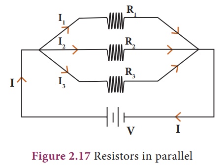
Consider three resistors
of resistances R1, R2 and R3 connected in
parallel. A source of e.m.f with voltage V is connected to the parallel
combination of resistors. A current I entering the combination gets divided
into I1, I2 and I3 through R1, R2
and R3 respectively as shown in Fig. 2.17.
The total current I is,
I = I1 + I2 + I3
By Ohm’s law, I1
= V/R1; I2 = V/R2; I3 = V/R3;
and I = V/RP
where RP is
the equivalent or effective resistance of the parallel combination.
(V/RP) = (V/R1)
+ (V/R2) + (V/R3) = Vx(1/R1 +1/R2
+1/R2)
1/RP = 1/R1
+1/R2 +1/R2
Thus, the reciprocal of
the effective resistance of resisters in parallel (1/RP) is equal to
the sum of the reciprocal of all the individual resistance.
Exercise 2.8
Figure shows three
resistors of values 1 Ω, 3 Ω , and 6 Ω connected in parallel to a 6 V dry cell.
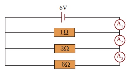
(a) What is the effective resistance of the three resistors?
(b) What is the p.d. across each resistor?
(c) What is the current measured by ammeters A1, A2
and A3?
Solution:
(a) 1/Rp = 1/R1 + 1/R2 + 1/R3
1/Rp = 1/1 + 1/3 + 1/6
1/Rp = 9/6
Rp =
0.667 W
(b) As the resistors are
in parallel, the p.d. across each resistor is equal,
p.d. = 6V
(c) (i) I = V/R = 6 V/6 Ω
= 1 A
Current measured by
ammeter A1 is 1 A
(ii) Current through 3 Ω resistor
= 6 V/3 Ω = 2 A
Current measured by
ammeter A2
= 1 A + 2 A = 3 A
(iii) Current through the 1 Ω resistor
= 6 V/1 Ω = 6 A
Current measured by
ammeter A3
= 6 A + 3 A = 9 A
Alternatively, since V =
6 V and effective resistence R = 0.667 W,
current measured by ammeter
A3 = 6 V /
0.667 Ω = 9 A
Related Topics