Chapter: Mechanical : Design of Transmission Systems : Bevel, Worm and Cross Helical Gears
Design Procedure for Worm Gear
WORM GEAR
Common terms used :
The following terms, in connection with the worm gearing, are important from the subject point of view :
1. Axial pitch. It is also known as linear pitch of a worm. It is the distance measured axially (i.e. parallel to the axis of worm) from a point on one thread to the corresponding point on the adjacent thread on the worm, as shown in Fig. 31.3. It may be noted that the axial pitch (pa) of a worm is equal to the circular pitch ( pc ) of the mating worm gear, when the shafts are at right angles.
2. Lead. It is the linear distance through which a point on a thread moves ahead in onerevolution of the worm. For single start threads, lead is equal to the axial pitch, but for multiple start threads, lead is equal to the product of axial pitch and number of starts. Mathematically,
Lead, l = pa . n
where pa = Axial pitch ; and
n = Number of starts.
3. Lead angle. It is the angle between the tangent to the thread helix on the pitch cylinder and the plane normal to the axis of the worm. It is denoted by λ.
A little consideration will show that if one complete turn of a worm thread be imagined to be unwound from the body of the worm, it will form an inclined plane whose base is equal to the pitch circumference of the worm and altitude equal to lead of the worm.
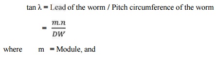
DW = Pitch circle diameter of worm.
The lead angle (λ) may vary from 9° to 45°. It has been shown by F.A. Halsey that a lead angle less than 9° results in rapid wear and the safe value of λ is 12½°.
4. Tooth pressure angle. It is measured in a plane containing the axis of the worm and is equal to one-half the thread profile angle as shown in Fig. Normal pitch. It is the distance measured along the normal to the threads between two corresponding points on two adjacent threads of the worm.
Mathematically,
Normal pitch, pN = pa.cos λ
Note. The term normal pitch is used for a worm having single start threads. In case of a worm having multiple start threads, the term normal lead (l N) is used, such that
lN = l . cos λ
6. Helix angle. It is the angle between the tangent to the thread helix on the pitch cylinder and the axis of the worm. It is denoted by αW,. The worm helix angle is the complement of
worm lead angle, i.e.
αW + λ = 90°
It may be noted that the helix angle on the worm is generally quite large and that on the worm gear is very small. Thus, it is usual to specify the lead angle (λ) on the worm and helix angle (αG) on the worm gear. These two angles are equal for a 90° shaft angle.
7. Velocity ratio. It is the ratio of the speed of worm (NW) in r.p.m. to the speed of the worm gear (NG) in r.p.m. Mathematically, velocity ratio,
V.R. = Nw / NG
Let l = Lead of the worm, and
DG = Pitch circle diameter of the worm gear.
We know that linear velocity of the worm,
vW = l . NW/60
where n = Number of starts of the worm.
DESIGN PROCEDURE FOR WORM GEAR:
1. Selection of the material:
2. Calculation of teeth:
ü Assume Z1 depending upon the number of stat.
ü Z2 = i X Z1
3. Calculation of diameter factor and lead angle
q = d1/mx
If not given assume q= 11
ɤ = tan-1 (z1/q)
4. Calculation of Tangential load:
Ft = (p/v) x K0
5. Calculation of Dynamic load:
Fd = Ft / cv
6. Calculation of Beam strength:
Fs = π mx b [ϭb] y
7. Calculation of Axial load:
Calculate axial load by equating Fd and Fs
8. Calculate b, d2, v.
9. Recalculation of beam strength
Fs = π mx b [ϭb] y1
10. Recalculation of dynamic load
Fd = Ft / cv
11. Check for beam strength:
If Fd ≤ Fd, design is satisfactory.
12. Calculation for maximum wear load:
Fw = d2. b . Kw
13. Check for wear strength:
If Fd ≤ Fw, design is satisfactory.
14. Calculate power loss and area:
15. Calculate basic dimensions.
Related Topics