Chapter: Mechanical : Design of Transmission Systems : Bevel, Worm and Cross Helical Gears
Bevel, Worm and Cross Helical Gears
BEVEL, WORM AND CROSS HELICAL GEARS
Common terms used:
1. Pitch cone. It is a cone containing the pitch
elements of the teeth.
2. Cone centre. It is the apex of the pitch
cone. It may be defined as that point where the axes of two mating gears intersect each other.
3. Pitch angle. It is the angle made by the pitch line with the axis of the shaft. It is denoted by ‘θP’.
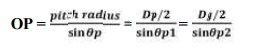
Cone distance. It is the length of the pitch
cone element. It is also called as a pitch cone radius. It is denoted by ‘OP’. Mathematically,
cone distance or pitch cone radius,
5.
Addendum angle. It is the angle subtended by the addendum of the tooth at the
cone centre. It is denoted by ‘α’ Mathematically, addendum angle,
α = tan–1
(a/OP)
where a =
Addendum, and OP = Cone distance.
6. Dedendum angle. It is the angle
subtended by the dedendum of the tooth at the cone centre. It is denoted by
‘β’. Mathematically, dedendum angle,
β = tan–1
(d/OP)
where d =
Dedendum, and OP = Cone distance.
7. Face angle. It is the angle subtended by
the face of the tooth at the cone centre. It is denoted by ‘φ’. The face angle is equal to the pitch angle plus
addendum angle.
8. Root angle. It is the angle subtended by
the root of the tooth at the cone centre. It is denoted by ‘θR’. It is equal to the pitch angle minus dedendum
angle.
9. Back (or normal) cone. It is
an imaginary cone, perpendicular to the pitch cone at the end of the tooth.
10.
Back cone
distance. It is the length of the back cone. It is denoted by ‘RB’. It is also called back cone radius.
11.
Backing. It is
the distance of the pitch point (P) from the back of the boss, parallel to the pitch point of the gear. It is denoted
by ‘B’.
Crown height. It is the distance of the crown
point (C) from the cone centre (O), parallel to the axis of the gear. It is denoted by ‘HC’.
13.
Mounting
height. It is the distance of the back of the boss from the cone centre. It is denoted by ‘HM’.
14.
Pitch
diameter. It is the diameter of the largest pitch circle.
15.
Outside
or addendum cone diameter. It is the maximum diameter of the teeth of the gear. It is equal to the diameter of
the blank from which the gear can be cut. Mathematically, outside diameter,
DO = DP +
2 a cos θP
where DP
= Pitch circle diameter,
a =
Addendum, and
θP =
Pitch angle.
16. Inside or dedendum cone diameter. The
inside or the dedendum cone diameter is given by
Dd = DP –
2d cos θP
where Dd = Inside diameter, and
d =
Dedendum.
Design procedure for Bevel Gear
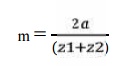
17. Calculation of gear ratio (i)
and pitch angle:
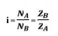
where, NA and NB = speed of
the driver and driven respectively, and ZA and ZB =
Number of teeth on driver and driven respectively.
18. Selection of material
Consulting
Table 5.3, knowing the gear ratio i, choose the suitable material.
19.
If not given, assume gear life (say 20000 hrs)
20.
Calculation
of initial design torque:
[Mt]
= Mt . K. Kd
where, [Mt] = transmission torque
K = Load
factor, Table 5.11
Kd =
Dynamic load factor, Table 5.12
Assume K.
Kd = 1.3 ( if not given)
21.
Calculation
of Eeq, [ϭb] and [ϭc]:
ü From
table 5.20 Calculate Eeq
ü Calculate
Design bending stress [ϭb]
[ϭb]
= (1.4 Kbl/n.Kσ) σ-1, for one rotation [ϭb] =
(Kbl/n.Kσ) σ-1, for both rotation
ü Calculate
Design contact stress [ϭc] by [ϭc]
= CB . HB. Kcl (or)
[ϭc]
= CR . HRC. Kcl
where, CB
CR = Coefficient of surface hardness from table 5.18
HB HRC =
Hardness number
22.Calculation if cone distance (a):
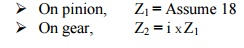
23. Select
number of teeth on gear and pinion:
24. Calculation of module:
Choose
standard module from table 5.8
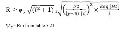
25. Revision of cone distance (m):
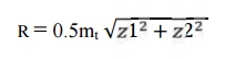
26. Calculate
b, d1av, v and ѱy :
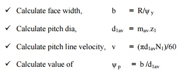
Calculate
face width, b = R/ѱy
Calculate
pitch dia, d1av =
mav.z1
Calculate
pitch line velocity, v =
(πd1avN1)/60
Calculate
value of ѱp = b /d1av
27. Selection of quality of gear:
Knowing
the pitch line velocity and acosulting table 5.22, select a suitable quality
of gear.
28.
Revision of design torque [Mt]: Revise K:
Using the
calculated value of ѱy revise the K value by using table 5.11
Revise Kd:
Using the
selected quality if gear and pitch line velocity, revise the Kd
value.
[Mt] = Mt . K. Kd
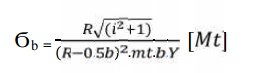
29. Check for bending:
Calculate
induced bending stress,
Compare
Ϭb and [Ϭb].
If
Ϭb ≤ [Ϭb], then design is safe.
30. Check for wear strength:
Calculate
induced contact stress,
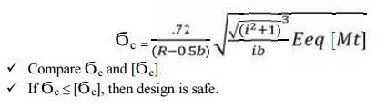
If Ϭc ≤
[Ϭc], then design is safe.
31. If the design is not satisfactory (ϭb >
[ϭb] and / or ϭc > [ϭc] ), then increase the module of face width value of the
gear material.
32. Check
for gear:
e. Check
for bending:
Using
Ϭb1.y1 and Ϭb1..y1,
Ϭb2 = 
Compare Ϭb2 and [Ϭb2].
If Ϭb2 ≤ [Ϭb2], then design is safe.
f. Check
for wear strength:
Calculate
induced contact stress will be same for pinion and gear,
So,
Ϭc2 = Ϭc
Compare Ϭc and [Ϭc]
If Ϭc ≤ [Ϭc], then design is safe
WORM GEAR
Common terms used :
The
following terms, in connection with the worm gearing, are important from the
subject point of view :
1. Axial pitch. It is also known as linear
pitch of a worm. It is the distance measured axially (i.e. parallel to the axis of worm) from a point on one thread to
the corresponding point on the adjacent thread on the worm, as shown in Fig.
31.3. It may be noted that the axial pitch (pa) of a worm is equal to the
circular pitch ( pc ) of the mating worm gear, when the shafts are at right
angles.
2. Lead. It is the linear distance
through which a point on a thread moves ahead in one revolution of the worm. For single start threads, lead is equal to
the axial pitch, but for multiple start threads, lead is equal to the product
of axial pitch and number of starts. Mathematically,
Lead, l =
pa . n
where pa = Axial pitch ; and
n =
Number of starts.
3. Lead angle. It is the angle between the
tangent to the thread helix on the pitch cylinder and the plane normal to the
axis of the worm. It is denoted by λ.
A little
consideration will show that if one complete turn of a worm thread be imagined
to be unwound from the body of the worm, it will form an inclined plane whose
base is equal to the pitch circumference of the worm and altitude equal to lead
of the worm.
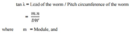
DW = Pitch circle diameter of worm.
The lead
angle (λ) may vary from 9° to 45°. It has been shown by F.A. Halsey that a lead
angle less than 9° results in rapid wear and the safe value of λ is 12½°.
4. Tooth pressure angle. It is measured in
a plane containing the axis of the worm and is equal to one-half the thread
profile angle as shown in Fig. Normal pitch. It is the distance measured along
the normal to the threads between two corresponding points on two adjacent
threads of the worm.
Mathematically,
Normal
pitch, pN = pa.cos λ
Note. The
term normal pitch is used for a worm having single start threads. In case of a
worm having multiple start threads, the term normal lead (l N) is used, such
that
lN = l .
cos λ
6. Helix angle. It is the angle between
the tangent to the thread helix on the pitch cylinder and the axis of the worm.
It is denoted by αW,. The worm helix angle is the complement of
worm lead
angle, i.e.
αW + λ =
90°
It may be
noted that the helix angle on the worm is generally quite large and that on the
worm gear is very small. Thus, it is usual to specify the lead angle (λ) on the
worm and helix angle (αG) on the worm gear. These two angles are equal for a
90° shaft angle.
7. Velocity ratio. It is the ratio of the
speed of worm (NW) in r.p.m. to the speed of the worm gear (NG) in r.p.m.
Mathematically, velocity ratio,
V.R. = Nw
/ NG
Let l = Lead of the worm, and
DG =
Pitch circle diameter of the worm gear.
We know
that linear velocity of the worm,
vW = l .
NW/60
where n =
Number of starts of the worm.
DESIGN PROCEDURE FOR WORM GEAR:
1.
Selection
of the material:
2.
Calculation
of teeth:
ü Assume Z1
depending upon the number of stat.
ü Z2
= i X Z1
3.
Calculation
of diameter factor and lead angle
q = d1/mx
If not
given assume q= 11
ɤ = tan-1
(z1/q)
4.
Calculation
of Tangential load:
Ft
= (p/v) x K0
5. Calculation
of Dynamic load:
Fd
= Ft / cv
6. Calculation
of Beam strength:
Fs
= π mx b [ϭb] y
7. Calculation
of Axial load:
Calculate
axial load by equating Fd and Fs
8.
Calculate
b, d2, v.
9.
Recalculation
of beam strength
Fs
= π mx b [ϭb] y1
10. Recalculation of dynamic load
Fd
= Ft / cv
11. Check for beam strength:
If Fd
≤ Fd, design is satisfactory.
12. Calculation for maximum wear
load:
Fw
= d2. b . Kw
13. Check for wear strength:
If Fd
≤ Fw, design is satisfactory.
14.
Calculate
power loss and area:
15.
Calculate
basic dimensions.
SOLVED PROBLEMS
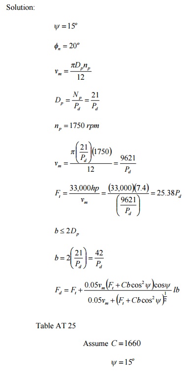
1. For continuous duty in a speed reducer, two
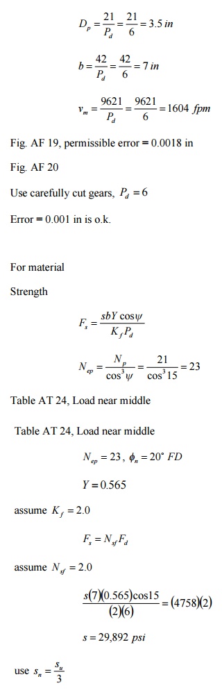
helical gears are to be rated at 7.4 hp at a pinion speed of 1750 rpm; mw » 2.75 ; the helix angle 15o ; 20o F.D. teeth in the
normal plane; let N p = 21 teeth, and keep b < 2Dp . Determine
the pitch, face, N g , and the material and heat treatment. Use
through-hardened teeth with a maximum of 250 BHM (teeth may be cut after heat
treatment).
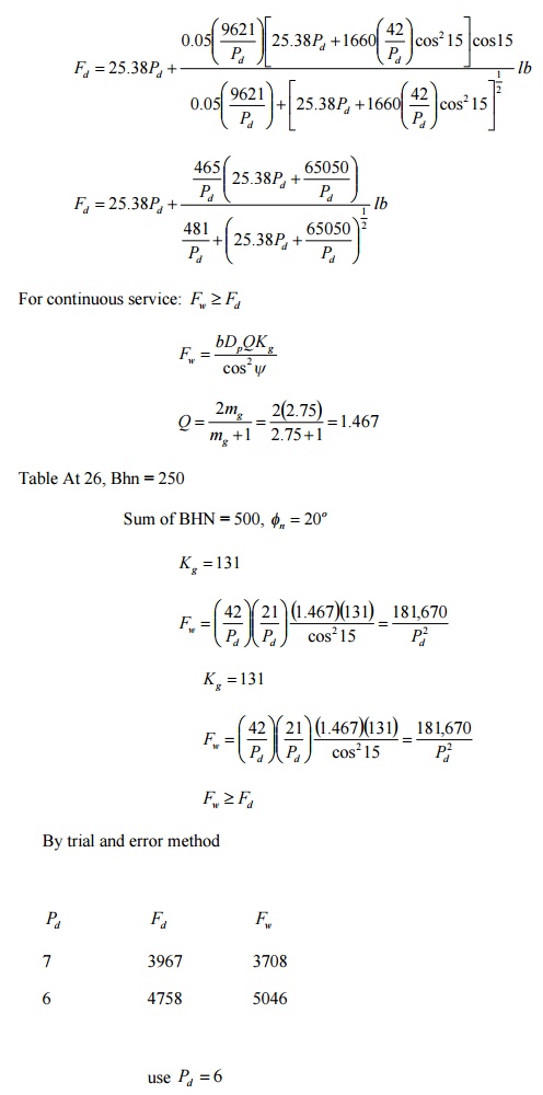
Solution:
su = 3(29,892) = 89,676 psi
Use
C1050, OQT 1100 F,
su = 122 ksi , BHN = 248 < 250
Ans.
Pd = 6
b = 7 in
N g = mw N p = (2.75)(21) = 58
Material.
C1050, OQT 1100 F
2. A
pair of helical gears, subjected to heavy shock loading, is to transmit 50 hp
at 1750 rpm of the pinion.; mg
y = 15 ; minimum
Dp = 4 3/4 in. ; continuous service, 24 hr/day; 20o F.D.
teeth in the normal plane, carefully cut; through-hardened to a maximum BHN = 350. Decide upon the pitch, face
width, material and its treatment.
Solution:
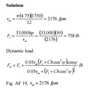
Fig. AF
19, vm = 2176 fpm
Permissible
error = 0.0014 in
Use
carefully cut gears, e = 0.001in , Pd = 5 as
standard
Table AT
25,
Steel and
steel, 20o FD
C = 1660
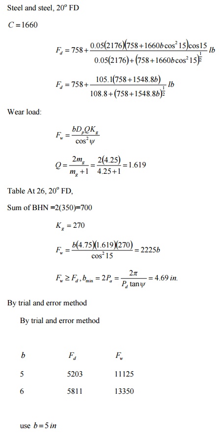
for 24
hr/day service, heavy shock loading
Nsf = 1.75
0.32955s = (1.75)(5203)
s = 27,629 psi
use sn = su 3
![]()
su = 3(27,629) = 82,887 psi
Table AT
9
Use 4150,
OQT 1200 F,
su = 159ksi , BHN = 331< 350
Ans.
Pd = 5
b = 5 in
Material.
4150, OQT 1200 F
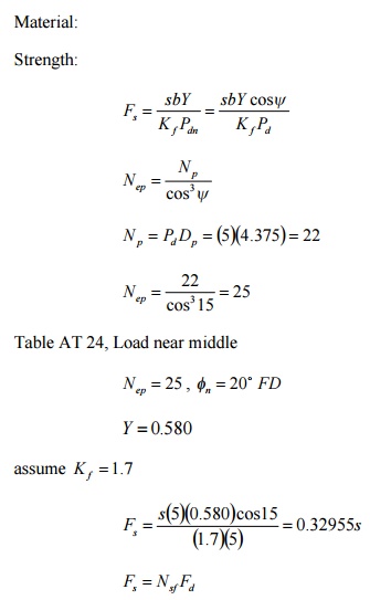
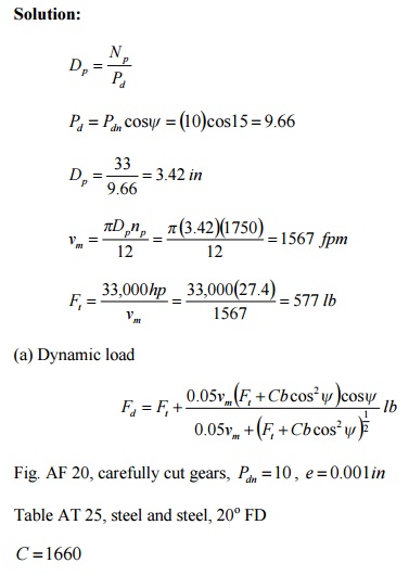
Two helical gears are used in a single reduction
speed reducer rated at 27.4 hp at a motor speed of 1750 rpm; continuous duty.
The rating allows an occasional 100 % momentary overload. The pinion has 33
teeth. Pdn = 10 , b = 2 in. , fn = 20 , y = 20 , mw
= 2.82 .
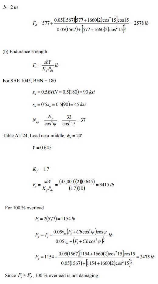
For both gears, the teeth are carefully cut from SAE 1045 with BHN = 180. Compute
(a) the dynamic load, (b) the endurance strength; estimate K
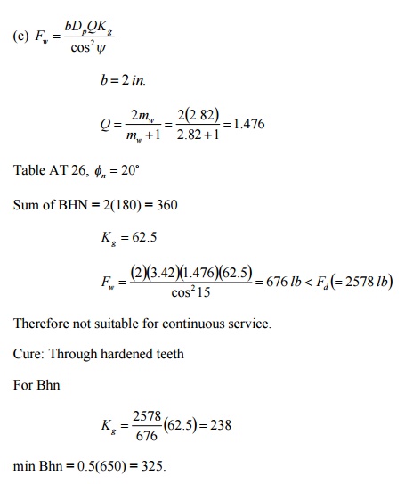
f = 1.7 . Also decide whether or not the 100 %
overload is damaging. (c) Are these teeth suitable for continuous service? If
they are not suitable suggest a cure. (The gears are already cut.)
Solution:
Related Topics