Chapter: Civil : Design Of Reinforced Concrete And Brick Masonry Structures- Design Of Reinforced Concrete Wall
Design Of Reinforced Concrete Wall
DESIGN
OF REINFORCED CONCRETE WALL
- Compression
member
- In
case where beam is not provided and load from the slab is heavy
- When
the masonry wall thickness is restricted
- Classified
as
o plain concrete wall, when
rein. < 0.4%
o Reinforced concrete wall,
when rein. > 0.4%
Load from slab is transferred as axial load to wall. When
depth is large, it is called RC wall. Design is similar to a RC column, breadth
equal to thickness of wall and depth equal to 1m.
- Axially
loaded wall
- Axially
loaded with uniaxial bending
General conditions:
Classification of concrete walls:
1. Plain
concrete wall
2. Reinforced
concrete wall
In plain concrete wall, the
reinforcement provided is less than 0.4% of c/s. In reinforced concrete wall,
the percentage of steel provided is greater than 0.4% and is designed similar
to reinforced concrete columns. Slenderness ratio is equal to
Least of (l/t or h/t), where,
l � effective length of wall, h � effective height of wall, t � thickness of wall
If ?
< 12, the
wall is short
and if ?
> 12, t
Braced and Unbraced:
Braced : When cross walls
are provided for the walls such that they can take lateral load and 2.5% of
vertical load, then the wall is braced. Otherwise, the wall is known as
unbraced wall.
Note: Other walls under special cases are,
i)
Cantilever wall
Shear walls -To take lateral loads [Take care
of flexure developed due to lateral loading on the structure, depth is provided
along the transverse direction]
Guidelines for RC wall:
1. The
limiting
slendernesslim)ifanyforunbraced(?wall is 30 and for braced wall is 45.
2. For short
bracedu =RC0.4.f ckwall.Ac+0.67 .f(?y.Ast <
12), P
3. For
short unbraced RC wall, along with the above axial load Pu, the moment due to
minimum eccentricity is checked for emin = t/20 or 20mm, where, M =
P x e.
For the above axial load and moment, the RC wall is
designed similar to RC column subjected to axial load and uniaxial moment.
4. Slender braced
wall (? <
45):
The additional moment due to additional eccentricity
as per Table 1 of SP16 is considered. Where the additional eccentricity,
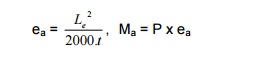
The additional moment due to eccentricity is
added with the moment on the column and moment on the wall. The wall is
designed for axial load with uniaxial moment.
5. For
slender unbraced wall Similar procedure[?limitedasincase4 isto 30 adopted.
6. Detailing
of reinforcement [IS456 Guidelines]:
a. For
plain concrete wall, minimum vertical steel is 0.12% for HYSD bars and 0.15%
for mild steel bar
b. For
RC wall, minimum vertical reinforcement is 0.4% of c/s
c. In
plain concrete wall, transverse steel is not required
d. In
RC wall, transverse steel is not required (not less than 0.4%)
e. Maximum
spacing of bars is 450mm or 3t, whichever lesser
f. The
thickness of wall in no case should be less than 100mm
g. If
thickness is greater than 200mm, double grid reinforcement is provided along
both the faces.
7. BS
8110 guidelines:
a. Horizontal
reinforcement same as IS456
b. Vertical
reinforcement not to be greater than 4%
When compression steel is greater than 2% of
vertical reinforcement, horizontal reinforcement of 0.25% for HYSD bars or 0.3%
of MS bars are provided. [As per IS456, it is 0.2% for HYSD bars and 0.3% for
mild steel bars].
d. The
diameter of transverse bars (horizontal) should not be less than 6mm or ?L/4.
8. Links
are provided when the compression steel is greater than 2%. Horizontal links
are provided for thickness less than 220mm. Diagonal links are provided when
thickness is greater than 220mm. The spacing of links
should be less than 2t and diameter of links Lnot/4. less than 6mm
or ?/4
1) Design a reinforced
concrete wall 3m height, 4m length between cross walls. The wall is 100mm thick
and carries a factored load of 600 kN/m length. Use M20 concrete and Fe415
steel.
Since cross walls are provided, the wall is braced.
?
= h/t or l/t
= 3000/120
or 4000/120
= 30
or 40
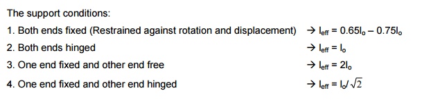
Assume both ends fixed (restrained against rotation and
displacement)
Leff = 0.75 lo where, lo is least
of length and height
= 0.75
x 3 = 2.25m
?
=
2250/100 = 22.5
> 12
?lim = 45 >
22.5 [? lim<] ? Accidental minimum eccentricity due to,
emin = t/20 or 20mm = 5 or 20mm
Therefore, moment due to accidental
eccentricity of 20mm is considered. Additional eccentricity due to slenderness,
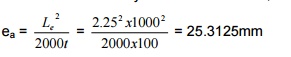
Total eccentricity = emin + ea = 20
+ 25.3 = 45.3mm
Moment Mu = Pu x 45.3 =
27.2 x 10⁶ Nmm
For the axial load and moment, RC wall is
designed similar to a RC column subjected to axial load and uniaxial moment.
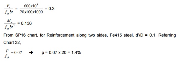
Area of steel = 1.4/100 x
100 x 1000 = 1400 mm2
Provide 16mm @ 140mm c/c as vertical compression bar
Horizontal -Provide a
nominal transverse reinforcement of 0.4% of c/s Ast = 0.4/100 x 1000 x 100 =
400 mm2
Provide 8mm @ 120mm c/c
Since vertical reinforcement is less than 2%, no
horizontal links are required.
2) A reinforced concrete wall of height 5m is
restrained in position and direction carrying a factored load of 600 kN and
factored moment of 25kNm at right angles to the plane of the wall. Use M20
concrete and Fe415 steel. Design the wall.

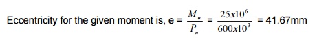
The eccentricity is compared
with emin. The larger of the two is added with additional
eccentricity due to slenderness, if any.
Assume l/d of 22. [Generally
assume l/d from 20 -25] d = 5000/22 = 227.27
Assume a thickness of 225mm
Leff = 0.75 x 5 = 3.75m
?act = 3750/225 =
16.67 > 12 The given wall is slender. emin = t/20 or 20mm
= 225/20
or 20mm
11.25mm or 20mm < 41.67mm Additional
eccentricity due to slenderness,
Total eccentricity = emin + ea =
41.67 + 31.25 = 72.92mm
Moment Mu = Pu x 72.92 = 600 x 1000
x 72.92 = 43.75 x 10⁶ Nmm
For the axial load and moment, RC wall is
designed similar to a RC column subjected to axial load and uniaxial moment.
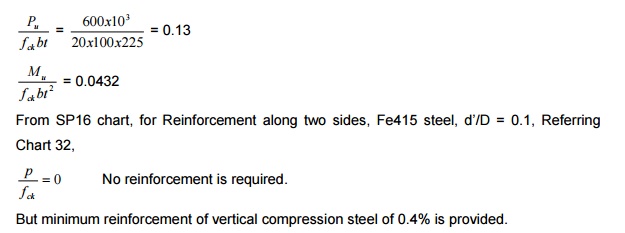
Area of steel = 0.4/100 x 225 x 1000 = 900 mm2
Provide 12mm @ 120mm c/c as vertical compression bar
Since thickness of wall is
225mm, reinforcement is provided on both faces of the wall. Therefore, provide
12mm @ 250mm c/c < 3t and 450mm
Horizontal -Provide a
nominal transverse reinforcement of 0.4% of c/s on both faces. Ast = 0.4/100 x
1000 x 100 = 400 mm2
Provide 8mm @ 120mm c/c
Since vertical reinforcement is less than 2%, no
horizontal links are required.
3) In the above problem, design the wall for
factored axial load of 1000kN and factored moment of 50kNm.
Pu = 1000kN, Mu = 50kNm
e = 50 x 106/1000 x 103
= 50mm
l/d = 22
[Generally l/d taken from 20 -25]
d = 5000/22 = 227.27mm
Adopt a thickness of 225mm.
leff = 0.75 x 5000 = 3750mm ?act = 3750/225 = 16.67 >
12 ?min = 45 > 16.67
Wall is slender.
Emin = t/20 or 20mm
= 225/20
or 20mm
= 11.25mm or 20mm < 41.67mm
Additional eccentricity due to slenderness,
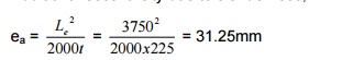
Total eccentricity = emin + ea
= 50 + 31.25 = 81.25mm
Moment Mu = Pu x 81.25
= 1000 x 1000 x 81.25 = 81.25 x 10⁶ Nmm
For the axial load and moment, RC wall is
designed similar to a RC column subjected to axial load and uniaxial moment.
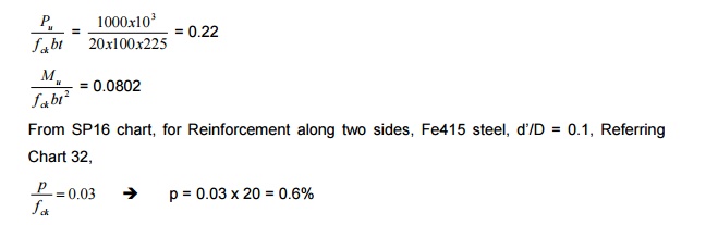
Area of steel = 0.6/100 x
225 x 1000 = 1350 mm2
Provide 16mm @ 140mm c/c as vertical compression bar
Horizontal -Provide a
nominal transverse reinforcement of 0.4% of c/s Area of steel = 0.4/100 x 225 x
1000 = 900 mm2
Since thickness of wall is
225mm, reinforcement is provided on both faces of the wall. Therefore, provide
12mm @ 250mm c/c < 3t and 450mm
Since vertical reinforcement is less than 2%,
no horizontal links are required.
Related Topics