Chapter: Civil : Design Of Reinforced Concrete And Brick Masonry Structures- Design Of Brick Masonry
Design Of Brick Masonry: Masonry Wall Subjected To Concentrated Load
Masonry
Wall Subjected To Concentrated Load
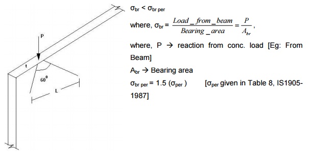
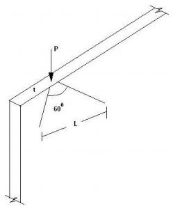
When concentrated load is applied on a masonry wall, the wall is checked for load bearing stress. Permissible stress in bearing is taken as 50% more than the value given in Table 7 of IS1905-1987
The
angle of dispersion below the concentrated load is 30o on each side.
Therefore, the actual stress is,
?act = P / A,
where, A �
Area for 1m run = L x t,
L �
Length of load dispersion = 2H/ tan 600 ,
H � Height of wall
For the wall to
be safeact<per?
in carrying the
lo
1) Design a solid wall of a mill building 3m height
securely tied with roof and floor units. The wall supports two beams on either
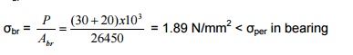
side exerting reactions of 30kN and 20kN. Thickness of wall is 230mm and the
beam bears on the wall for 115mm (width of beam). Neglect load due to self
weight.
Abr = 230 x 115 = 26450 mm2
The values given
in Tableper
in8bearingare. increased by
Therefore, assume H1 grade of mortar and brick of
compressive strength 15 N/mm2. ?per = 1.31 N/mm2
?per br = 1.5 x 1.31 = 1.965 N/mm2
Check for compressive stress:
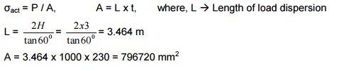
A = 3.464 x 1000 x 230 = 796720 mm2
?act = 50x103 / 796720= 0.063 N/mm2
![]()
?per = 1.31 N/mm2
Kst = 0.89
KA = 1
Ksh = 1.06
?per modified = Kst x KA x Ksh x per?
=
0.89 x 1 x 1 x 1.31 = 1.1659 N/mm2 > act?[0.063 N/mm2]
The wall is safe in carrying a concentrated load with H1
mortar and brick of compressive strength 15N/mm2.
2) Design the exterior wall of a workshop building 3.6m
height carrying steel trusses at 4.5m spacing. The wall is securely tied at
roof and floor levels. The wall is of thickness 200mm and the truss bears on
the wall for 200mm and load from the truss is 30kN.
[Length is considered only for piers and cross walls] Abr
= 200 x 200 = 40000 mm2
Assume M1 mortar and brick of compressive strength 10
N/mm2. Check for compressive stress:
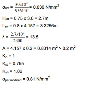
?ac = P/A
L = 2H / tan 600o =
4.157m
A = 4.157 x 103 x 200 =
956110mm2
3) In the above problem, design the wall if
piers are available below the truss and size of pier is 200 x 400mm.
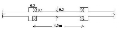
Here, we need to take the length. If the
truss fully rests on pier, bearing area,
Abr = 80000 mm2
P = 30 x 103 N
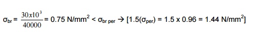
?br = 30x103 200x400
?br = 0.375N/mm2 < ?br per -
> [1.5(0.96) = 1.44 N/mm2]
Using M1 mortar and brick of compressive
strength 10N/mm2, Check for compressive stress:
?ac = P/A
L = 2H/tan 600 = 4.16m
Heff = 0.75 x 3.6 = 2.7m
Leff = 0.8 x L = 0.8 x 4.5 = 3.6m
te = Sc x t
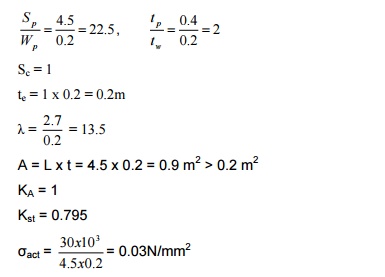
?per modified = = 1 x 1 x 0.795 x
1.06 x 0.96 = 0.8089 N/mm2
Hence the wall is safe with M1 mortar and brick of
compressive strength 10N/mm2.
Related Topics