Chapter: Civil : Structural Analysis : Deflection Of Determinate Structures
Deflection Of Determinate Structures
DEFLECTION OF DETERMINATE STRUCTURES
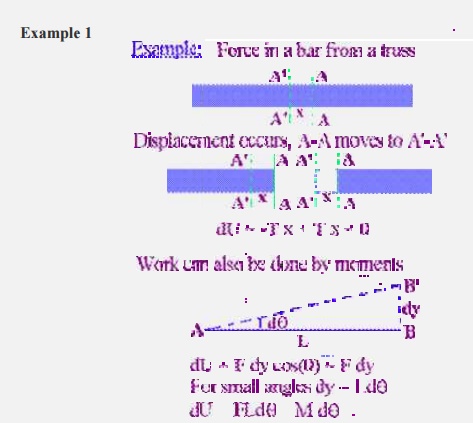
The physical quantity work is
defined as the product of force times a conjugate d isplacement, i.e., a
displacement in the same d irection as the force we are considering. We are
familiar with real work, i.e., the product of a r eal force and a real
displacement, i.e., a force and a displacement that both actually occur. The
situ ation is illustrated in Part 1 of the following figure:
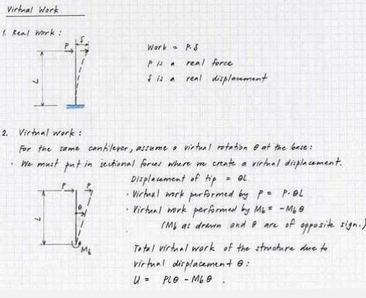
We can extend the
concept of real work to a definition of virtual work, which is the product of a
real force and a conjugate displacement, either real or virtual. In Part 2 of
the example shown above, we assume that the cantilever column loaded with force
P undergoes a virtual rotation of magnitude at its base. We compute the virtual
work corresponding to this virtual displacement by summing the products of real
forces times conjugate virtual displacements.
For this
calculation, we must introduce unknown sectional forces at those locations
where we have cut the structure to create the virtual displacement. In the
example shown above, therefore, we have introduced bending moment at the base,
Mb. For completeness, we would also have to
introduce a shear
force V and an axial force N at the base of the column, but, as we shall see,
there is no component of virtual displacement conjugate to these forces. They
have therefore not been shown in the example.
We calculate the
virtual displacements of the structure corresponding to all known and unknown
forces. For a rotation at the base, horizontal translation of the tip of the
cantilever is � L. We then multiply force times displacement and sum these
products to obtain the following expression for virtual work corresponding to
the assumed virtual displacement:
U = P � L �
- Mb �
We treat the
virtual work done by force Mb as negative since the direction of Mb
as drawn is opposite to the direction of the virtual rotation .
The principle of virtual
work states that a system of real forces is in equilibrium if and only if the
virtual work performed by these forces is zero for all virtual displacements
that are compatible with geometrical boundary conditions.
For the example
given in the previous subsection, this implies that the virtual work of the
simple cantilever, U, must be zero for the system to be in equilibrium:
U = P � L �
- Mb � = 0
Since
is nonzero, it follows that Mb = P � L, which is precisely the familiar
expression for
bending moment at the base of a cantilever
loaded with force P at its tip.
A more general mathematical statement of the
principle of virtual work is as follows:
Let Qi be a set of real loads acting on a given
structure
Let Ri be the corresponding real support
reactions
Let Mi, Vi, and Ni be the sectional forces
(bending moment, shear, and axial force) introduced at
the locations where the structure has been cut
to allow it to undergo a virtual displacement.
Let
Qi, Ri, Mi,
Vi, and Ni be virtual
displacements compatible with the geometrical
boundary conditions and conjugate to the forces
defined previously.
Then the structure is in equilibrium if and and
only if:
(Qi� Qi) + (Ri� Ri) + (Mi� Mi) + (Vi� Vi) + (Ni� Ni) = 0
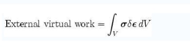
Virtual Work
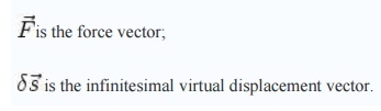
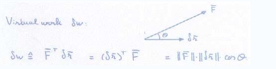
Virtual work is defined as the f ollowing line integral

Where
C is the path
or curve tra versed by the object, keeping all constraints sati sfied;
the force vector :
the infinitesimal v
irtual displacement vector :
Virtual work is therefore a special case of mechanical work. For the work to
be called virtual, the motion undergone by the system must be compatible
with the system's const raints, hence the use of a virtual displacement.
One of the key ideas of Lagrangian
mechanics is that the virtual work done by th e constraint forces should be
zero. This is a reasonable assumption, for otherwise a physical system might
gain or lose energy simply by being constrained (imagine a bead on a stationary
hoop moving faster and faster for no apparent reason)!
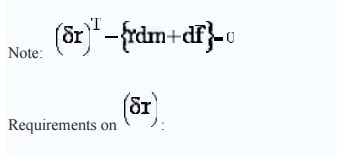
The idea of virtual work also plays
a key role in interpreting D'Alembert's principle:
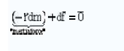
Equilibrium of forces
('staic' tre atment)
 virtual wor k produced by inertia force
 virtual work rpodu ced by net applied force.
-
compatible with the kinematic
constraints, but otherwise arbitrary
-
instantaneous
-
increasingly small
'Lagrange form of
d'Alembert's Principle'
This formalism is convenient, as the
constraint (non-working) loads disappear. ( forces, torques)
Where u iis the vector of
independent degrees-of-freedom.
Example (i)
The motivation for
introducing virtual work can be appreciated by the following simple example
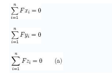
from statics of particles. Supposee a particle is in equilibrium under a set of
force s Fxi, Fyi, Fzi i
=
1,2,...n:
Multiplying the three
equations with the respective arbitrary constants ?x, ?y, ?z :
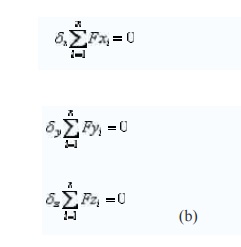
When the arbitrary constants ?x, ?y, ?z are thought of as virtual displacements of the particle, then
the left-hand-sides of (b) represent the virtual work. The total virtual work
is:
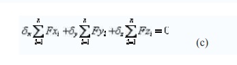
Since the preceding
equality is valid for arbitrary virtual displacements, it leads back to the
equilibrium equations in (a). The equation (c) is called the principle of
virtual w ork for a particle. Its use is equivalent to the use of many
equilibrium equations.
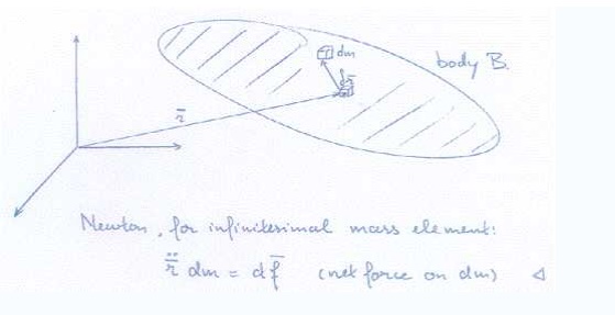
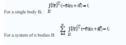
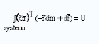
Applying to a deformable body in equilibrium that undergoes compatible displa cements and deformations, we can find the tottal virtual work by including both internal and external forces acting on the particles. If the mat erial particles experience compatible displacements and deformations, the work done by internal stresses cancel out, and the net virtual w ork done reduces to the work done by the applied external forces. The total virtual work i n the body may also be found by the volume integral of the product of stresses
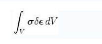
Thus, the principle of virtual wo rk for a
deformable body is:
This relation is equivalent to the set of
equilibrium equations written for the particles in the deformable body. It is
valid irrespective of material behaviour, and hence leads to powerful
applications in structural analysi s and finite element analysis.
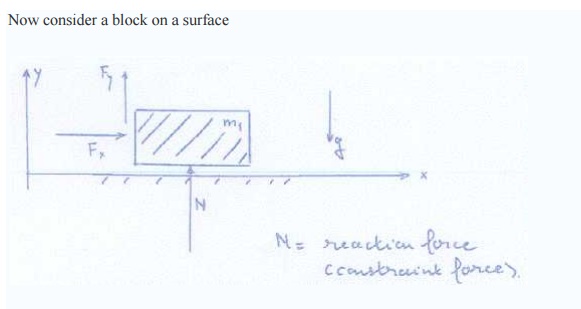
Now consider a block on a surfa ce
Applying formula (c) gives:
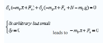
Observe virtual work formalism leads directly to Newton's
equation of motion i n the
kinematically allowable directio n.
Example (ii)
Two bodies connected by a rotary joint
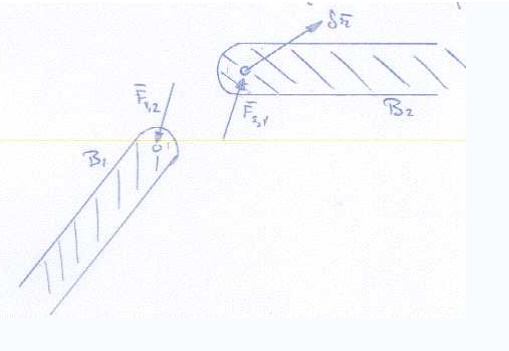
Virtual wotk produced by these constranit loads:
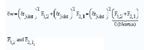
drop out of the exp ression
By assuming the contributions to virtual work
produced by all forces in and an all system elements, the constraint loads dis
appear.
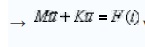
For multi-body system, the derivation of the
equatios of motion now becomes much more simple.
Degree of freedom or Kine matic Indeterminacy
Members of structure deform due to external
loads. The minimum number of parameters required to
uniquely descr ibe the deformed shape of
structure is called
'Degree of Freedom'.
Displacements and rotations at  various p oints in structure are the
parameters considered in describing the deformed shape of a structure. In
framed structure the deformation at joints is first computed and then shape of
deformed structure. Deformation at intermediate points on the structure is
expressed in terms of end deformations. At supports the deformations
corresponding to a reaction is zero. For example hinged support of a two dimensional
system permits only rotation and translation along x and y directions are zero.
Degree of freedom of a structure is expressed as a number equal to number of
free displacements at all joints. For a two dimensional structure each rigid
joint has three displacements as shown in
various p oints in structure are the
parameters considered in describing the deformed shape of a structure. In
framed structure the deformation at joints is first computed and then shape of
deformed structure. Deformation at intermediate points on the structure is
expressed in terms of end deformations. At supports the deformations
corresponding to a reaction is zero. For example hinged support of a two dimensional
system permits only rotation and translation along x and y directions are zero.
Degree of freedom of a structure is expressed as a number equal to number of
free displacements at all joints. For a two dimensional structure each rigid
joint has three displacements as shown in
In case of three dimensional structure each rigid joint has
six displacement.
� Expression
for degrees of freedom
1. 2D
Frames: NDOF = 3NJ - NR NR ?3
2. 3D
Frames: NDOF = 6NJ - NR NR ?6
3. 2D
Trusses: NDOF= 2NJ - NR NR ?3
4. 3D
Trusses: NDOF = 3NJ - NR NR ?6
Where,
NDOF is the number of degrees of freedom
In 2D analysis of frames some times axial deformation is
ignored. Then NAC=No. of axial condition is deducted from NDOF
Conditions
of Equilibrium and Static Indeterminacy
A body is said to be under static
equilibrium, when it continues to be under rest after application of loads.
During motion, the equilibrium condition is called dynamic equilibrium. In two
dimensional system, a body is in equilibrium when it satisfies following
equation.
SFx=0 ; SFy=0 ; SMo=0 ---1.1
To use the equation 1.1, the force components along x and y
axes are considered. In three dimensional system equilibrium equations of
equilibrium are
SFx=0 ; SFy=0 ; SFz=0;
SMx=0 ; SMy=0 ; SMz=0; ----1.2
To use the equations of equilibrium (1.1 or 1.2), a free body
diagram of the structure as a whole or of any part of the structure is drawn.
Known forces and unknown reactions with assumed direction is shown on the
sketch while drawing free body diagram. Unknown forces are computed using
either equation 1.1 or 1.2
Before analyzing a structure, the
analyst must ascertain whether the reactions can be computed using equations of
equilibrium alone. If all unknown reactions can be uniquely determined from the
simultaneous solution of the equations of static equilibrium, the reactions of
the structure are referred to as statically determinate. If they cannot
be determined using equations of equilibrium alone then such structures are
called statically indeterminate structures. If the number of
unknown reactions are less than the number of equations of equilibrium
then the structure is statically unstable.
The degree of indeterminacy is
always defined as the difference between the number of unknown forces and the
number of equilibrium equations available to solve for the unknowns. These
extra forces are called redundants. Indeterminacy with respect external forces
and reactions are called externally indeterminate and that with respect
to internal forces are called internally indeterminate.
A general procedure for
determining the degree of indeterminacy of two-dimensional structures are given
below:
NUK=
Number of unknown forces
NEQ=
Number of equations available
IND=
Degree of indeterminacy
IND= NUK
- NEQ
Indeterminacy of Planar Frames
For entire structure to be in equilibrium, each member and
each joint must be in equilibrium (Fig. 1.9)
NEQ =
3NM+3NJ
NUK=
6NM+NR
IND= NUK - NEQ =
(6NM+NR)-(3NM+3NJ)
IND=
3NM+NR-3NJ ----- 1.3
Related Topics