Chapter: Digital Principles and System Design : Synchronous Sequential Logic
Counters
COUNTERS
In digital logic and computing, a counter is a
device which stores (and sometimes displays) the number of times a particular
event or process has occurred, often in relationship to a clock signal. In
practice, there are two types of counters:
·
up counters which increase (increment) in value
·
down counters which decrease (decrement) in value
Counters
Types
In electronics, counters can be implemented quite easily using
register-type circuits such as the flip-flop, and a wide variety of designs
exist,
ü Asynchronous
(ripple) counters
ü Synchronous
counters
ü Johnson
counters
ü Decade
counters
ü Up-Down
counters
ü Ring
counters
Each is useful for different applications. Usually, counter
circuits are digital in nature, and count in binary, or sometimes binary coded
decimal. Many types of counter circuit are available as digital building
blocks, for example a number of chips in the 4000 series implement different
counters.
ü Asynchronous (ripple) counters
The simplest counter circuit is a single D-type flip flop,
with its D (data) input fed from its own inverted output. This circuit can
store one bit, and hence can count from zero to one before it overflows (starts
over from 0). This counter will increment once for every clock cycle and takes
two clock cycles to overflow, so every cycle it will alternate between a
transition from 0 to 1 and a transition from 1 to 0. Notice that this creates a
new clock with a 50% duty cycle at exactly half the frequency of the input
clock. If this output is then used as the clock signal for a similarly arranged
D flip flop (remembering to invert the output to the input), you will get
another 1 bit counter that counts half as fast. Putting them together yields a
two bit counter:
ü Synchronous counters
Where a stable count value is important across several bits,
which is the case in most counter systems, synchronous counters are used. These
also use flip-flops, either the D-type or the more complex J-K type, but here,
each stage is clocked simultaneously by a common clock signal. Logic gates
between each stage of the circuit control data flow from stage to stage so that
the desired count behavior is realized. Synchronous counters can be designed to
count up or down, or both according to a direction input, and may be presetable
via a set of parallel "jam" inputs. Most types of hardware-based
counter are of this type.
A simple way of implementing the
logic for each bit of an ascending counter (which is what is shown in the image
to the right) is for each bit to toggle when all of the less significant bits
are at a logic high state. For example, bit 1 toggles when bit 0 is logic high;
bit 2 toggles when both bit 1 and bit 0 are logic high; bit 3 toggles when bit
2, bit 1 and bit 0 are all high; and so on.
ü Johnson counters
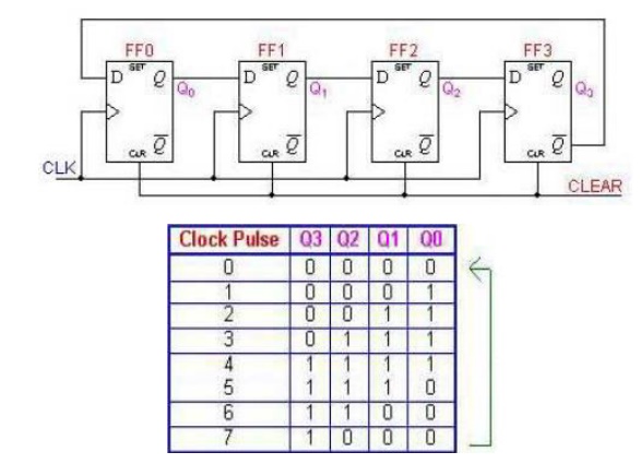
A Johnson counter is a special case of shift
register, where the output from the last stage is inverted and fed back as
input to the first stage. A pattern of bits equal in length to the shift
register thus circulates indefinitely. These counters are sometimes called
"walking ring" counters, and find specialist applications, including
those similar to the decade counter, digital to analogue conversion, etc.

The apparent disadvantage of this
counter is that the maximum available states are not fully utilized. Only eight
of the sixteen states are being used.
ü Decade counters
Decade counters are a kind of
counter that counts in tens rather than having a binary representation. Each
output will go high in turn, starting over after ten outputs have occurred.
This type of circuit finds applications in multiplexers and demultiplexers, or
wherever a scanning type of behaviour is useful. Similar counters with
different numbers of outputs are also common.
ü Up-Down Counters
It is a combination of up counter
and down counter, counting in straight binary sequence. There is an up-down
selector. If this value is kept high, counter increments binary value and if
the value is low, then counter starts decrementing the count. The Down counters
are made by using the complemented output to act as the clock for the next
flip-flop in the case of Asynchronous counters. An Up counter is constructed by
linking the Q out of the J-K Flip flop and putting it into a Negative Edge
Triggered Clock input. A Down Counter is constructed by taking the Q output and
putting it into a Positive Edge Triggered input
ü Ring Counters
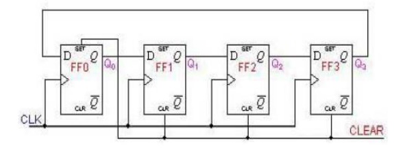
A ring counter is basically a circulating shift
register in which the output of the most significant stage is fed back to the
input of the least significant stage. The following is a 4-bit ring counter
constructed from D flip-flops. The output of each stage is shifted into the
next stage on the positive edge of a clock pulse. If the CLEAR signal is high,
all the flip -flops except the first one FF0 are reset to 0. FF0 is preset to 1
instead.

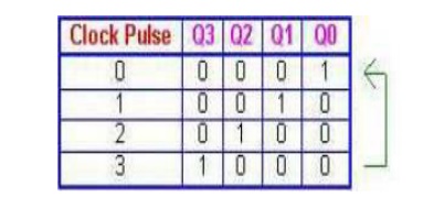
Since the count sequence has 4 distinct states,
the counter can be considered as a mod-4 counter. Only 4 of the maximum 16
states are used, making ring counters very inefficient in terms of state usage.
But the major advantage of a ring counter over a binary counter is that it is
self-decoding. No extra decoding circuit is needed to determine what state the
counter is in.

Applications of counters:
•
Watches
•
Clocks
•
Alarms
•
Web browser
refresh
Related Topics