Chapter: Electrical Drives & Control : Conventional and Solid State Speed Control Of D.C Drives
Conventional Methods of Speed Control
Conventional Methods of Speed Control
1. Speed control of DC Shunt Motors:
o By varying the resistance in the armature circuit
o By varying the flux (field)
o By varying the applied Voltage
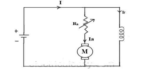
2. Armature Resistance Control
ü Speed of the motor is directly proportional to the back emf Eb
Eb = V- IaRa.
· That is when supply voltage V and armature resistance Ra are kept constant, speed is directly proportional to armature current Ia. Thus if we add resistance in series with armature, Ia decreases and hence speed decreases.
Greater the resistance in series with armature, greater the decrease in speed.
Advantages:
· Simple method of speed control
Disadvantages:
· The change in speed with the change in load becomes large.
· More power is wasted in this controller resistance.
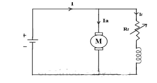
2. Field flux control:
· Speed of the motor is inversely proportional to flux. Thus by decreasing flux speed can be increased and vice versa.
· To control the flux, a rheostat is added in series with the field winding, as shown in the circuit diagram.
· Adding more resistance in series with field winding will increase the speed, as it will decrease the flux.
· Field current is relatively small and hence I2R loss is small, hence this method is quiet efficient.
· Though speed can be increased by reducing flux with this method, it puts a limit to maximum speed as weakening of flux beyond the limit will adversely affect the commutation.
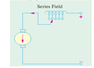
2. Speed control of DC Series Motors:
1. Armature Resistance Control
· The controlling resistance is connected directly in series with the supply to the motor
· The power loss in the control resistance of dc series motor can be neglected because this control method is utilized for a large portion of time for reducing the speed under light load condition.
· This method of speed control is most economical for constant torque.
· This method of speed control is employed for dc series motor driving cranes, hoists, trains etc
2. Field Control Method:
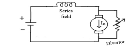
a) Field Divertor Method:
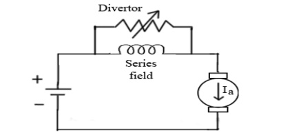
· A veritable resistance is connected parallel to the series field as shown in fig.
· This variable resistor is called as divertor, as desired amount of current can be diverted through this resistor and hence current through field coil can be decreased.
· Hence flux can be decreased to desired amount and speed can be increased.
b) Armature Divertor Method:
· Divertor is connected across the armature as in fig.
· For a given constant load torque, if armature current is reduced then flux must increase.
Ta α ØIa
This will result in increase in current taken from the supply and hence flux Ø will increase and subsequently speed of the motor will decrease.
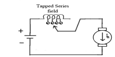
C) Tapped field Control:
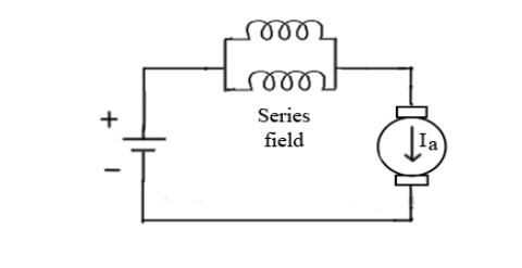
D) Paralleling field Control:
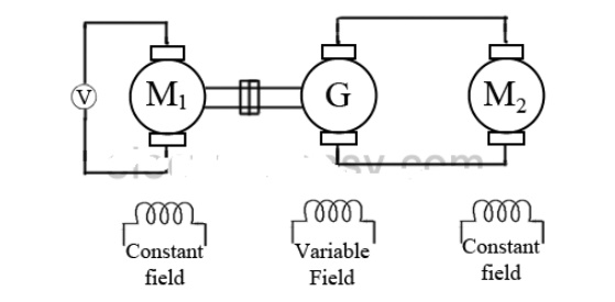
3. Ward Leonard Control System:
This system is used where very sensitive speed control of motor is required (e.g electric excavators, elevators etc.) The arrangement of this system is as required in the figure beside.
M2 is the motor whose speed control is required. M1 may beany AC motor or DC motor with constant speed. G is the generator directly coupled to M1.
In this method the output from the generator G is fed to the armature of the motor M2 whose speed is to be controlled.
The output voltage of the generator G can be varied from zero to its maximum value, and hence the armature voltage of the motor M2 is varied very smoothly.
Hence very smooth speed control of motor can be obtained by this method.
Advantages:
Full forward and reverse speed can be achieved.
A wide range of speed control is possible
Short time overload capacity is large
The armature current of the motor is smooth.
Disadvantages:
High initial cost
The overall efficiency is low, less than 80%
Costly foundation and a large amount of space is required
The drive produces noise
It requires frequent maintenance.
Related Topics