Chapter: Computer Architecture : Overview & Instructions
Computer Architecture: Instructions
INSTRUCTIONS
Instruction format
The instruction format of an
instruction is usually depicted in a rectangular box symbolizing the bits of
the instruction as they appear in memory words or in a control register. An
instruction format defines the layout of the bits of an instruction, in terms
of its constituent parts. The bits of an instruction are divided into groups
called fields. The most common fields found in instruction formats are:
·
An operation code field that specifies the
operation to be performed.
·
An address field that designates a memory address
or a processor register.
· A mode field
that specifies the way the operand or the effective address is determined
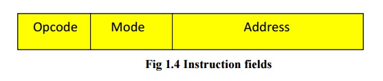
Fig 1.4
Instruction fields
Other special fields are
sometimes employed under certain circumstances. The operation code field of an
instruction is a group of bits that define various processor operations, such
as add, subtract, complement and shift. Address fields contain either a memory
address field or a register address. Mode fields offer a variety of ways in
which an operand is chosen.
There are mainly four types of instruction formats:
·
Three address instructions
·
Two address instructions
·
One address instructions
·
Zero address instructions
Three address instructions
Computers with three address
instructions formats can use each address field to specify either a processor
register or a memory operand. The program in assembly language that evaluates
X= (A+B)*(C+D) is shown below, together with comments that explain the register
transfer operation of each instruction.
Add R1, A, B R1ßM [A] + M [B]
Add
R2, C, D R2ßM [C] + M [D]
Mul
X, R1,R2 M [X]ßR1 + R2
It is assumed that the computer
has two processor registers, R1 and R2. The symbol M[A] denotes the operand at
memory address symbolized by A. the advantage of the three address format is
that it results in short programs when evaluating arithmetic expressions. The
disadvantage is that the binary coded instructions require too many bits to
specify three addresses. An example of an commercial computer that uses three
address instructions is the Cyber 170.The instruction formats in the Cyber
computer are restricted to either three register address fields or two register
address fields and one memory address field.
Two address instructions
Two address instructions are the
most common in commercial computers. Here again each address field can specify
either a processor register or a memory word. The program to evaluate X=
(A+B)*(C+D) is as follows:
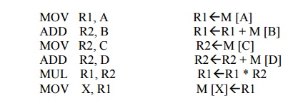
The MOV instruction moves or
transfers the operands to and from memory and processor registers. The first
symbol listed in an instruction is assumed to be both a source and the
destination where the result of the operation is transferred.
One address instructions
One address instructions use an
implied accumulator (AC) register for all data manipulation. For multiplication
and division there is a need for a second register. However, here we will
neglect the second register and assume that the AC contains the result of all
operations. The program to evaluate X= (A+B)*(C+D) is
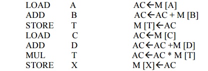
All operations are done between
the AC register and a memory operand. T is the address of a temporary memory
location required for storing the intermediate result. Commercially available
computers also use this type of instruction format.
Zero address instructions
A stack organized computer does
not use an address field for the instructions ADD and MUL. The PUSH and POP
instructions, however, need an address field to specify the operand that
communicates with the stack. The following program shows how X=(A+B)*(C+D) will
be written for a stack organized computer.(TOS stands for top of stack.)
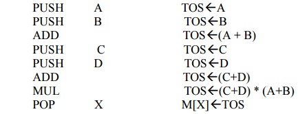
To evaluate arithmetic
expressions in a stack computer, it is necessary to convert the expression
into reverse polish notation. The name “zero address” is given to this
type of computer because of the absence of an address field in computational
instructions.
Related Topics