Chapter: Digital Principles and System Design : Combinational logic
Combinational circuits
COMBINATIONAL LOGIC
PRE-REQUISITE
DISCUSSION
The term combinational comes to us from mathematics. In
mathematics a combination is an unordered set, which is a formal way to say
that nobody cares which order the items came in.
Logic circuits for digital systems may be combinational or
sequential. A combinational circuit consists of logic gates whose outputs at
any time are determined from only the present combination of inputs. A
combinational circuit performs an operation that can be specified logically by
a set of Boolean functions. In contrast, sequential circuits employ storage
elements in addition to logic gates. Their outputs are a function of the inputs
and the state of the storage elements.
COMBINATIONAL
CIRCUITS
A combinational circuit is one where the output at any time
depends only on the present combination of inputs at that point of time with
total disregard to the past state of the inputs. The logic gate is the most
basic building block of combinational logic. The logical function performed by a
combinational circuit is fully defined by a set of Boolean expressions. The
other category of logic circuits, called sequential logic circuits, comprises
both logic gates and memory elements such as flip-flops. Owing to the presence
of memory elements, the output in a sequential circuit depends upon not only
the present but also the past state of inputs.
A combinational circuit consists of input
variables, logic gates, and output variables. Combinational logic gates react
to the values of the signals at their inputs and produce the value of the
output signal, transforming binary information from the given input data to a
required output data.
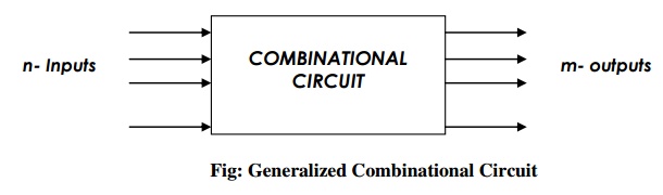
The n-input binary variables come from an external
source; the m- output variables are produced by the internal combinational
logic circuit and go to an external destination.
ANALYSIS PROCEDURE
The analysis of a combinational circuit requires
that we determine the function that the circuit implements. The analysis can be
performed manually by finding the Boolean functions or truth table or by using
a computer simulation program.
The first step in the analysis is to make that the given
circuit is combinational or sequential. Once the logic diagram is verified to
be combinational, one can proceed to obtain the output Boolean functions or the
truth table.
To obtain
the output Boolean functions from a logic diagram,
· Label all
gate outputs that are a function of input variables with arbitrary symbols or
names. Determine the Boolean functions for each gate output.
· Label the
gates that are a function of input variables and previously labeled gates with
other arbitrary symbols or names. Find the Boolean functions for these gates.
·
Repeat the process in step 2 until the outputs of
the circuit are obtained.
· By repeated
substitution of previously defined functions, obtain the output Boolean
functions in terms of input variables.
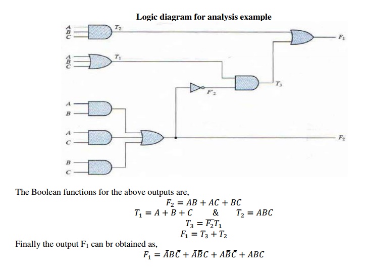
Logic diagram for analysis example
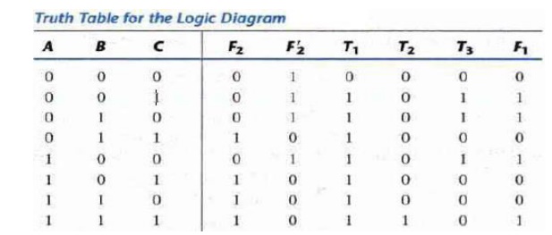
To obtain the truth table directly from the logic diagram
without going through the derivations of Boolean functions,
·
Determine the number of input variables in the circuit. For n-inputs, form the
2n possible input combinations and list the binary numbers from 0 to
2n-1 in a table.
·
Label the outputs of selected gates with arbitrary
symbols.
· Obtain
the truth table for the outputs of those gates which are a function of the
input variables only.
· Proceed
to obtain the truth table for the outputs of those gates which are a function
of previously defined values until the columns for all outputs are determined.
DESIGN PROCEDURE
The design of combinational circuits starts from the
specification of the design objective and culminates in a logic circuit diagram
or a set of Boolean functions from which the logic diagram can be obtained. The
procedure involved involves the following steps,
ü From the
specifications of the circuit, determine the required number of inputs and
outputs and assign a symbol to each.
ü Derive
the truth table that defines the required relationship between inputs and
outputs.
ü Obtain
the simplified Boolean functions for each output as a function of the input
variables.
ü Draw the logic diagram and verify the correctness of the design.
Related Topics