Chapter: Solid State Drives : Design of Controllers For Drives
Closed Loop Control with Current and Speed Feedback
Closed Loop Control With Current And Speed Feedback
Closed loop control improves on the drives performance by increasing speed of response and improving on speed regulation. So the functions of closed loop control is that ωn is increased, ε is reduced, ts is reduced, and Speed Regulation (SR) is reduced. A closed loop speed control scheme is shown below
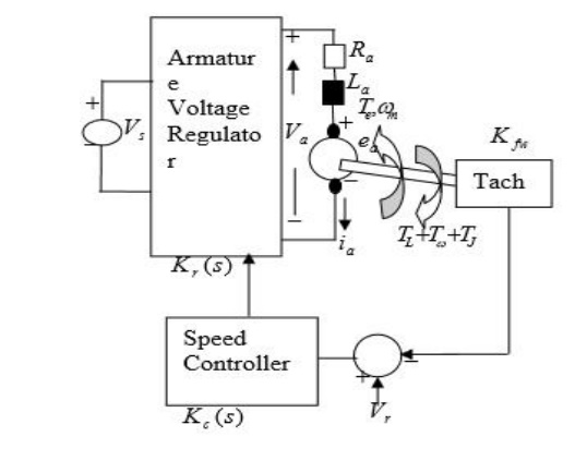
Schematic Diagram of the Closed Loop Speed Control
Where, Kfω is the tachometer feedback gain
Kc(s) is the speed controller gain
Kr(s) is the armature voltage regulator gain
The block diagram representation of the control configuration is shown below.
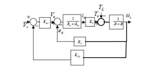
Block Diagram of the Closed Loop Speed Control.
If the tachometer loop does not contain a filter, the feedback gain can be a constant designated as Kfw
Kcw(s) = Kcwp + KcwI/ s +sKcwd
Where,
Kcwd is the proportional gain component of Kcw(s)
Kcwp is the integral gain component of Kcw(s) & Kcwd
Three possible controller configurations are possible:
1.For KcwI & Kcwd zero Kcw(S) = Kcwp Which is a Proportional Controller
2. For Kcwp & Kcwd zero Kcw(S) = KcwI/S Which is an Integral Controller
3. For Kcwd zero Kcw(S) = Kcwp+ KcwI/S Which is a Proportional Integral Controller
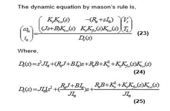
Now taking the Proportional Controller as a case study, with Kcw(S) = Kcwp , the dynamic equation is,
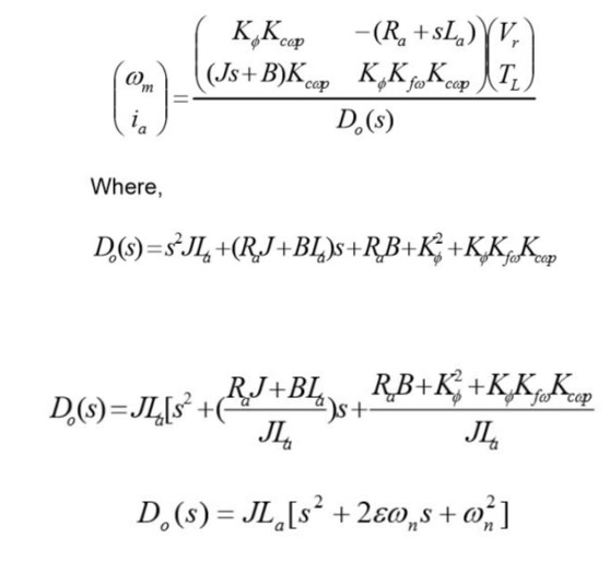
Last Equation is a second order system
The Natural Frequency of Oscillation, ωn is,
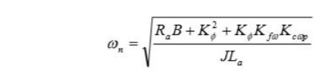
This is always higher than the open loop case due to the factor Kф ,KfѠ, KcѠp
The Damping Ratio, ε , is
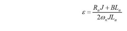
This is lower than in the open loop case due to the increase in ωn
Speed Regulation (SR) is also derived as
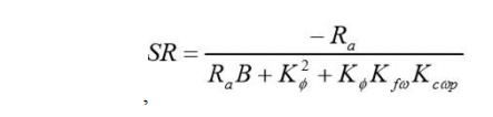
SR is also lower than in the open loop case due to the factor Kф ,KfѠ, KcѠp . This is an indication of a better drive performance.
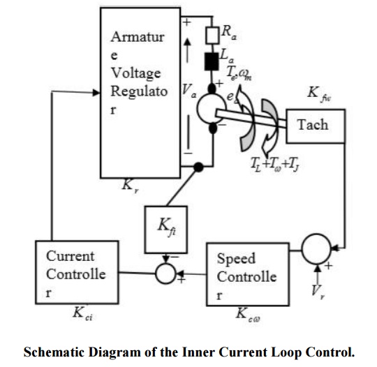
Inner Current Loop Control
Improvement in speed control can be obtained with Inner Current Loop Control method, whereby armature current is fed back to the input. A closed loop speed control scheme with inner current control is shown in Figure.
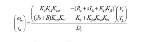
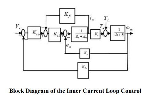
Designating K1ci+Kr=Kci the block diagram representation of the control configuration is shown in Figure.
The dynamic equation is,
Related Topics