Chapter: Computer Architecture : Processor and Control Unit
Building Data Path and Control Implementation Scheme
BUILDING
DATA PATH AND CONTROL IMPLEMENTATION SCHEME
Datapath
Components of the processor that perform
arithmetic operations and holds data.
Control
· Components
of the processor that commands the datapath, memory, I/O devices according to
the instructions of the memory.
Building a Datapath
· Elements
that process data and addresses in the
CPU - Memories, registers, ALUs.
· MIPS
datapath can be built incrementally by considering only a subset of
instructions
· 3
main elements are
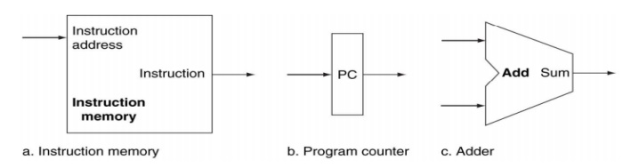
Fig.
3.1 Datapath
· A
memory unit to store instructions of a program and supply instructions given an
address. Needs to provide only read access (once the program is loaded).- No
control signal is needed
· PC
(Program Counter or Instruction address register) is a register that holds the
address of the current instruction
Ø A
new value is written to it every clock cycle. No control signal is required to
enable write
Ø Adder
to increment the PC to the address of the next
instruction
· An
ALU permanently wired to do only addition.
No extra control signal required
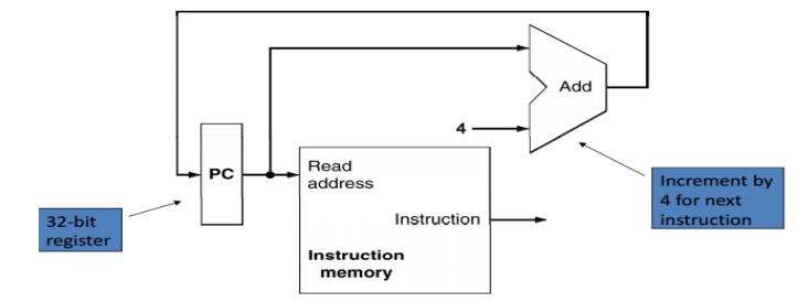
Fig.
3.2 Datapath portion for Instruction Fetch
Types of Elements in the Datapath
State element:
· A
memory element, i.e., it contains a state
·
E.g., program counter, instruction
memory Combinational element:
· Elements
that operate on values
· Eg
adder ALU E.g. adder, ALU
Elements
required by the different classes of instructions
· Arithmetic
and logical instructions
· Data
transfer instructions
· Branch
instructions
R-Format ALU Instructions
· E.g.,
add $t1, $t2, $t3
· Perform
arithmetic/logical operation
· Read
two register operands and write register
result
Register file:
· A
collection of the registers
· Any
register can be read or written by specifying
the number of the register
· Contains
the register state of the computer
Read from register
· 2
inputs to the register file specifying the numbers
•
5 bit wide inputs for the 32 registers
· 2
outputs from the register file with the read values
•
32 bit wide
· For
all instructions. No control required.
Write to register file
· 1
input to the register file specifying the number 5 bit wide inputs for the 32 registers
· 1
input to the register file with the value to be written 32 bit wide
· Only
for some instructions. RegWrite control signal.
ALU
· Takes
two 32 bit input and produces a 32 bit output
· Also,
sets one-bit signal if the results is 0
· The
operation done by ALU is controlled by a 4 bit control signal input. This is
set according to the instruction .
Related Topics