Chapter: Engineering Mechanics : Basics and Statics of Particles
Basics and Statics of Particles
What is
Engineering Mechanics?
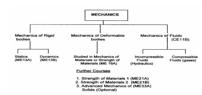
Mechanics is the study of forces that act on bodies and the
resultant motion that those bodies experience. With roots in physics and
mathematics, Engineering Mechanics is the basis of all the mechanical sciences:
civil engineering, materials science and engineering, mechanical engineering
and aeronautical and aerospace engineering. Engineering Mechanics provides the
"building blocks" of statics, dynamics, strength of materials, and
fluid dynamics. Engineering mechanics is the the discipline devoted to the solution
of mechanics problems through the integrated application of mathematical,
scientific, and engineering principles. Special emphasis is placed on the
physical principles underlying modern engineering design.
Engineering Mechanics students are also encouraged to engage in
undergraduate research with a faculty member. As a result, Engineering
Mechanics students are prepared for careers at the forefront of a wide variety
of fields, including the aerospace, electronics, automotive, manufacturing,
software, and computer industries. The curriculum also provides excellent
preparation for graduate school in many different engineering disciplines.
Introduction to Mechanics
1 Mechanics
Laws of Mechanics
1 Newton’s law
2 Lami’s theorem
3 Parallelogram Law of forces
4 Law of Triangle of Forces
5 Vectorial representation of
forces
6 How Forces Are Represented
7 Addition of Forces
8 Dot Product
9 Resultant of Three Force Vectors
10 Equation of equilibrium
11 Forces in Space
12 Equilibrium of a particle in
space
13 The principle of
transmissibility
14 Single Equivalent Force
BASICS AND STATICS OF PARTICLES
Introduction
to Mechanics
Continuum
mechanics is concerned with motion and deformation of material objects, called
bodies, under the action of forces. If these objects are solid bodies, the
respective subject area is termed solid mechanics, if they are fluids, it is
fluid mechanics or fluid dynamics. The mathematical equations describing the
fundamental physical laws for both solids and fluids are alike, so the
different characteristics of solids and fluids have to be expressed by
constitutive equations. Obviously, the number of different constitutive
equations is huge considering the large number of materials. All of this can be
written using a unified mathematical framework and common tools. In the
following we concentrate on solids. Continuum mechanics is a phenomenological
field theory based on a fundamental hypothesis called continuum hypothesis. The
governing equations comprise material independent principles namely,
Mechanics
v Body of
Knowledge which Deals with the Study and Prediction of the State of Rest or
Motion of articles and Bodies under the action of Forces
v Kinematics, being a purely geometrical
description of motion and deformation
of material bodies;
v Kinetics, addressing forces as external
actions and stresses as internal reactions;
v Balance equations for
conservation of mass, momentum and energy; and material dependent laws, the
v Constitutive equations.
Altogether,
these equations form an initial boundary value problem.
Laws of Mechanics
1 Newton’s law
Law I
Each body
remains in its state of rest or motion uniform in direction until it is made to
change this state by imposed forces.
Law II
The
change of motion is proportional to the imposed driving force and occurs along
a straight line in which the force acts.
Law III
To every
action there is always an equal reaction: or the mutual interactions of two
bodies are always equal but directed contrary.
2 Lami’s theorem
It states
that, “If there forces acting at a point are in equilibrium, each force will be
proportional to the sine of the angle between the other two forces.”
Suppose
the three forces P, Q and Rare acting at a point 0 and they are in equilibrium
as shown in Fig.
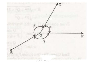
Let a = Angle between force P and Q.
β =Angle
between force Q and R.
y = Angle
between force R and P.
Then according to Lame’s theorem, P is proportional
sine of angle between Q and R a sin β. P / sin β = constant.
Similarly Q / sin γ = constant,
R / sin a = constant P / sin β = Q / sin γ = R / sin a
Example-1: In a jib crane, the jib
and the tie rod are 5 m and 4 m long resp ectively. the height of crane post in
3 m and the ti es red remains horizontal. Determine the for ces produced in jib
and tie rod when a load of 2 kn in suspended at the crane head.
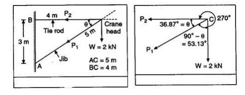
Solution: From
figure
sin q =
3/5 = 0.6
q = 36.87o
Let P1 and P2 be the forces developed in jib and tie rod respectively. the three forces P1, P2 and W are shown in figure with the angle between the forces calculated from the given directions. The line of action of forces P1, P2 and weigh W meet at the point C, and therefore Lami’s theorem is
applicable.
That gives:
∴P1/sin 270o
= P2/sin 53.13o = 2/si n36.87o
P1
= 2 × sin 270 o / sin 36.87o = 2 × 1/0. = –3.33 kN
P2
= 2 × sin 53.13 o / sin 36.87o = 2 × 0.8 / 0.6 = 2.667 kN
The –ve
sign indicates that the direction of force P1 is opposite to that
shown in figure obviously the tie rod will be under tension and jib will in
compression.
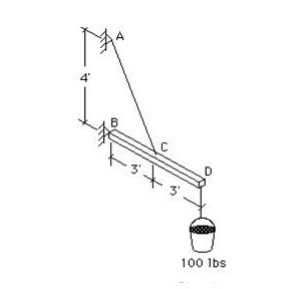
Examples-2: A string
ABCD w hose extremity A is fixed has weights W1 and W2 attached
to it at B and C, and passes round a smooth
peg at D carrying a weight of 800 N at the free end E shown in Figure. If in a
state of equilibrium, BC is horizontal and AB and CD make angles of 150o
and 120o respectively wit h BC, make calculation for (a) The tension
i n portion AB, BC, CD and DE of the string. (b) t he value of weights W1
and W2 (c) The load o n the peg at D
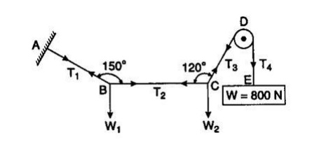
Solution: Let T1, T2,
T3, T4 be the
tension in segments AB, BC, CD and DE of the string.
Under
equilibrium condition, T5 = T4 = 800 N
Applying
Lami’s theorem at point B,
T1/sin90o
= T2/sin120o = W1/sin150o
T1
= T2 sin 90o / sin 120o = 400 × 1/0.866 =
461.89 N
W1
= T2 sin 150o / sin 120o = 400 × 0.5 / 0.866 =
230.95 N
(c) Load on peg at D = T3 sin 60o
+ W
= 800 sin
60o + 800 = 692.82 + 800
= 1492.82 N
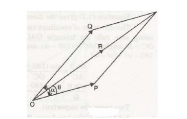
3 Parallelogram Law of forces
The law
of parallelogram of forces is used to determine the resultant* of two forces
acting at a point in a plane. It states, “If two forces, acting at a point be
represented in magnitude and direction by the two adjacent sides of a
parallelogram, then their resultant is represented in magnitude and direction
by the diagonal of the parallelogram passing through that point.”
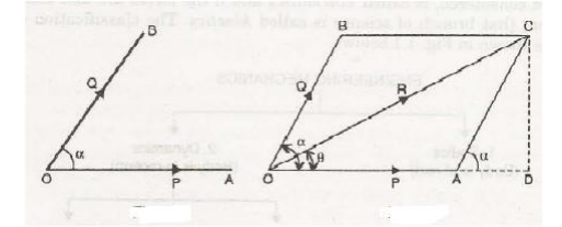
Let two
forces P and Q act at a point 0 as shown in Fig. 1.3. The force P is
represented in magnitude
and
direction by OA whereas the force Q is presented in magnitude and direction by
OB. Let the angle between the two forces be ‘a’. The resultant of these two
forces will be obtained in magnitude
and
direction by the diagonal (passing through O) of the parallelogram of which OA
and OB are two adjacent sides. Hence draw the parallelogram with OA and OB as
adjacent sides as shown in Fig. The resultant R is represented by OC in
magnitude and direction.
Magnitude of Resultant (R)
From C
draw CD perpendicular to OA produced.
Let a = Angle between two forces P and
Q = LAOB
Now < DAC = < LAOB (Corresponding angles)
In
parallelogram OACB, AC is parallel and equal to OB .
AC=Q.
In
triangle ACD,
AD = AC
cos a = Q cos a and CD =AC sin a= Q sin a.
In
triangle OCD,
OC2
= OD2 + DC2.
But OC = R, OD
= OA +AD = P + Q cos a and DC =Q sin a
R 2
= (P + Q cos a)2 + (Q sin a)2 = p2 + Q2
cos2 a+ 2PQ cos < X+ Q2 sin2 a
= p2
+ Q2 (cos2 a+ sin2 a)+ 2PQ cos a
= P2
+ Q2 + 2PQ cos a
R = √ p2
+ Q2 + 2PQ cos a
Direction of Resultant
Let θ = Angle made by resultant with OA.
Then from
triangle OCD,
tan θ =
CD / OD = Q sin a / P + Q cos a θ = tan -1 ( Q sin a / P + Q cos a)
The
direction of resultant can a lso be obtained by using sine rule [In triangle O
AC, OA = P, AC = Q, OC = R, angle O AC = (180 - a), angle ACO = 180- [θ + 180 -
a] = (a- θ)]
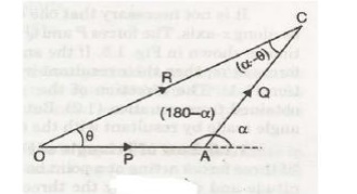
sin θ /
AC = sin (180 –a) OC = sin (a – θ) / OA sin θ / Q = sin (180 – a) / R = sin (a
– θ) / P
Two cases
are important.
1st Case. If the two forces P and Q act
at right angles, then a = 90° we get the m agnitude of resultant as
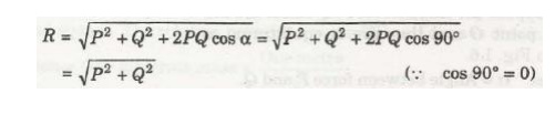
the
direction of resultant is obtai ned as θ = tan -1 ( Q sin a / P + Q
sin a)
= tan -1
( Q sin 900 / P + Q cos 90 0 ) = tan -1 Q /P
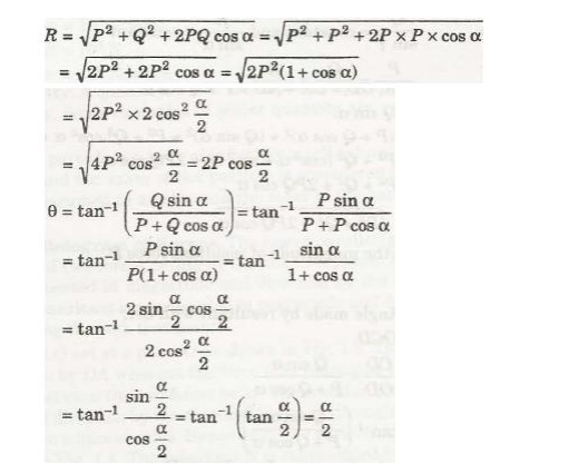
2nd Case. The two forces P and Q are equal
and are acting at an angle a betwee n them. Then the magnitude and direction of resul tant is given as
4 Law of
Triangle of Forces
It states
that, “if three fo rces acting at a point be represented in magnitude and
direction by the three sides of a triangle, take n in order, they will be in
equilibrium.”
5 Vectorial representation of forces
A force
can be represented as a vector. Forces and vectors share three major
characteristics:
v Magnitude
v Direction
v Location
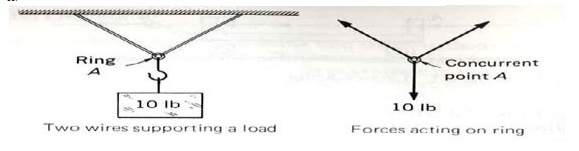
The
simple support structure in Figure can be used to illustrate the three
characteristics that make a force equivalent to a vector.
6 How Forces Are Represented
There are
two ways in which forces can be represented in written form:
1. Scalar
Notation
2. Vector
Notation
3. The
method used depends on the type of problem being solved and the easiest
approach to finding a solution.
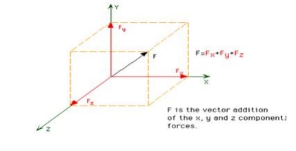
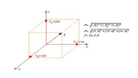
Scalar
notation is useful when describing a force as a set of orthogonal force
components. For example: Fx = 15N, Fy = 20N, Fz = 10N.
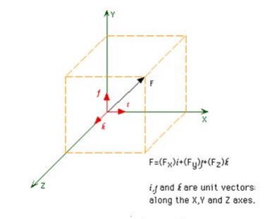
Vector
notation is useful when vector mathematics are to be applied to a problem, such
as addition or multiplication. Vector notation is somewhat simple in form:
F = 15i +
20j + 10k N.
The N
term represents the unit of force, Newtons in this instance.
7 Addition of Forces
Multiple
forces can be applied at a point. These forces are known as concurrent forces
and can be added together to form a resultant force. If the component forces
are orthogonal, then the magnitude of the resultant force can be determined by
taking the Square Root of the Sum of the Squares (SRSS). The SRSS method is an
extension of the Pythagorean Theorem to three dimensions.
8 Dot Product
Sometimes
it is useful t o know how much of a force is acting in a dire ction other than
the X,Y,or Z direction. Such a case might involve a bolted connection with a
slotted hole, as shown in Figure.
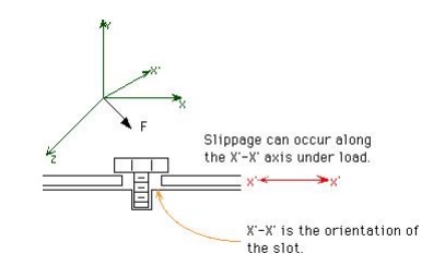
Suppose
that the force i n Figure 1.5.1 was F=40i + 10j + 30kNewtons, and that the X'
axis was oriented along the unit vect or e=0.6i + 0.5j - 0.624k. The projection
of F onto X' would be the force component acting in the direction of the slot.
Now consider the possibility that the connection would slip if Fx' was greater
th an 35 N. Will the connection slip? The dot p roduct will help us answer this
question.
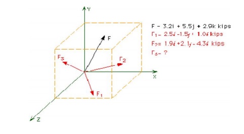
9 Resultant of Three Force Vectors
Three
force vectors (F1, F2, F3) are simmultaneously applied at point A. The
resultant of these three forces is F. Determin e F3 such that: F = 3.2i + 5.5j + 2.9k. Write F3 in
vector notation.
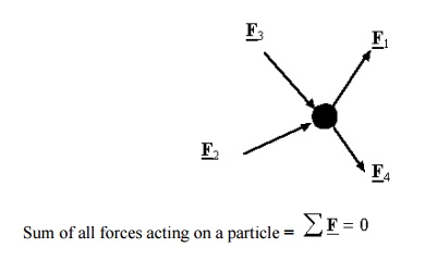
10 Equation of equilibrium
A
particle is in equilibrium if it is stationary or it moves uniformly relative
to an inertial frame of reference. A body is in equilibrium if all the
particles that may be considered to comprise the body are in equilibrium. One
can study the equilibrium of a part of the body by isolating the part for
analysis. Such a body is called a free body. We make a free body diagram and
show all the forces from the surrounding that act on the body. Such a diagram
is called a free-body diagram. For example, consider a ladder resting against a
smooth wall and floor. The free body diagram of ladder is shown in the right.
When a body is in equilibrium, the resultant of all forces acting on it is
zero. Thus that resultant force R and the resultant couple M R
are both zero, and we have the equilibrium equations
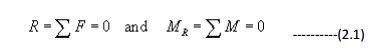
These
requirements are necessary and sufficient conditions.
Let us understand equation for different type of
force systems.
Types of system of forces 1. Collinear forces :
In this
system, line of action of forces act along the same line is called collinear
forces. For example consider a rope is being pulled by two players as shown in
figure F1 F2
2. Coplanar forces
When all
forces acting on the body are in the same plane the forces are coplanar
3. Coplanar Concurrent force system
A
concurrent force system contains forces whose lines-of action meet at same one
point. Forces may be tensile (pulling)
or Forces may be compressive (pushing)
4. Non Concurrent Co-Planar Forces
A system
of forces acting on the same plane but whose line of action does not pass
through the same point is known as non concurrent coplanar forces or system for
example a ladder resting against a wall and a man is standing on the rung but
not on the center of gravity.
5. Coplanar parallel forces
When the
forces acting on the body are in the same plane but their line of actions are
parallel to each other known as coplanar parallel forces for example forces
acting on the beams and two boys are sitting on the sea saw.
6. Non coplanar parallel forces
In this
case all the forces are parallel to each other but not in the same plane,for
example the force acting on the table when a book is kept on it.
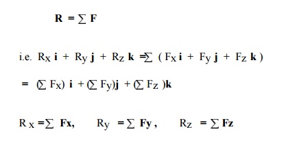
11 Forces in Space
The
resultant, R of two o r more forces
in space is obtained by summing their rectangular components i.e.
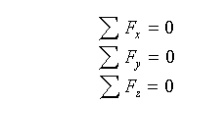
12 Equilibrium of a particl e in space
A
particle is in equilibrium if the resultant of ALL forces acting on the
particle is equal to zero
(Newton’s
first law is that a bod y at rest is not subjected to any unbalanced force s).
Equilibrium equations in component form: In a rectangular coordinate
system the equilibrium equations can
be represented by three scalar equations:
To apply
equilibrium equations we must account for all known and unknown forces acting
on the particle. The best way to do this is to draw a free-body diagram of the
particle.
13 The principle of transmissibility
If a
force, acting at a point on a rigid body, is shifted to any other point which
is on the line of action of the force, the external effect of the force on the
body remains unchanged".
14 Single Equivalent Force
When a
number of forces are acting on a rigid body, then these forces can be replaced
by a single force which has. the same effect on the rigid body as that of all
the forces acting together, then this single, force is known as 'Single
Equivalent Force'. This single equivalent force is also known as resultant of
several forces. Hence a single force which can replace a number of forces
acting on a rigid body, without causing any change in external effects on the
body, is known as single equivalent force (or resultant force )
Related Topics