Definition, Logical symbol, Formula, Truth table - Basic Logic Gates | 11th Computer Science : Chapter 2b : Boolean Algebra
Chapter: 11th Computer Science : Chapter 2b : Boolean Algebra
Basic Logic Gates
Basic Logic Gates:
A gate is a basic electronic
circuit which operates on one or more signals to produce an output signal.
There are three fundamental gates namely AND, OR and NOT. The other logic gates
like NAND, NOR, XOR and XNOR are derived gates which are derived from the
fundamental gates. NAND and NOR gates are called Universal gates, because the
fundamental logic gates can be realized through them.
1. AND Gate
The AND gate can have two or more
input signals and produce an output signal.
The output is "true"
only when both inputs are "true", otherwise, the output is
"false". In other words the output will be 1 if and only if both
inputs are 1; otherwise the output is 0. The output of the AND gate is
represented by avariable say C, where A and B are two and if input boolean
variables. In boolean algebra, a variable can take either of the values '0' or
'1'. The logical symobl of the AND gate is
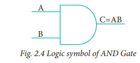
One way to symbolize the action of
an AND gate is by writing the boolean function.
C = A AND B
In boolean algebra the multiplication
sign stands for the AND operation. Therefore, the output of the AND gate is
C = A . B or
simply C = AB
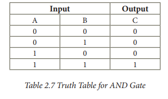
Read this as "C equals A AND
B". Since there are two input variables here, the truth table has four
entries, because there are four possible inputs : 00, 01, 10 and 11.
For instance if both inputs are 0,
C = A . B
=0 . 0
=0
The truth table for AND Gate is
2. OR Gate
The OR gate gets its name from its
behaviour like the logical inclusive "OR". The output is "true"
if either or both of the inputs are "true". If both inputs are
"false" then the output is "false". In otherwords the
output will be 1 if and only if one or both inputs are 1; otherwise, the output
is 0. The logical symbol of the OR gate is
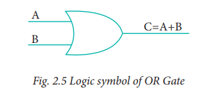
The OR gate output is
C = A OR B
We use the + sign to denote the OR
function. Therefore,
C = A + B
Read this as "C equals A OR
B".
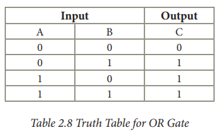
For instance, if both the inputs
are 1
C = A + B = 1 + 1 = 1
The truth table for OR gate is
3. NOT Gate
The NOT gate, called a logical
inverter, has only one input. It reverses the logical state. In other words the
output C is always the complement of the input. The logical symbol of the NOT
gate is
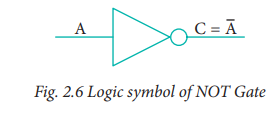
The boolean function of NOT gate
is
C = NOT A
In boolean algerbra, the overbar
stands for NOT operation. Therefore,
Read this as "C equals NOT
A" or "C equals the complement of A".
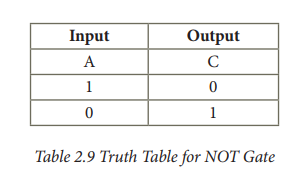
If A is 0,
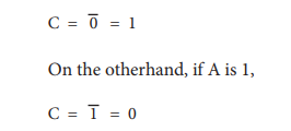
The truth table for NOT gate is
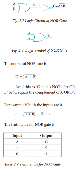
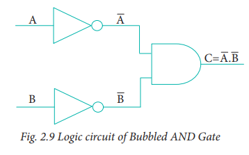
4. NOR Gate
The NOR gate circuit is an OR gate
followed by an an inverter. Its output is "true" if both inputs are
"false" Otherwise, the output is "false". In other words,
the only way to get '1' as output is to have both inputs '0'. Otherwise the
output is 0. The logic circuit of the NOR gateis
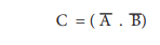
5. Bubbled AND Gate
The Logic Circuit of Bubbled AND
Gate
In the above circuit, invertors on
the input lines of the AND gate gives the output as
This circuit can be redrawn as the
bubbles on the inputs, where the bubbles represent inversion.
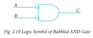
We refer this as bubbled AND gate.
Let us analyse this logic circuit for all input possiblities.
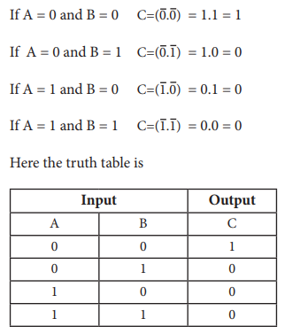
You can see that, a bubbled AND
gate produces the same output as a NOR gate. So, You can replace each NOR gate
by a bubbled AN D gate. In other words the circuits are interchangeable.
Therefore
Which establishes the De Morgan's
first theorem.
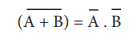
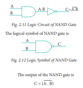
6. NAND Gate
The NAND gate operates an AND gate
followed by a NOT gate. It acts in the manner of the logical operation
"AND" followed by inversion. The output is "false" if both
inputs are "true", otherwise, the output is "true". In
otherwords the output of the NAND gate is 0 if and only if both the inputs are
1, otherwise the output is 1. The logice circuit of NAND gate is
Read this as "C" equals
NOT of A AND B" or "C" equals the complement of A AND B".
For example if both the inputs are
1
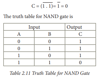
The truth table for NAND gate
7. Bubbled OR Gate
The logic circuit of bubbled OR
gate is
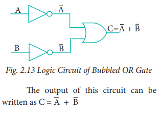
The above circuit can be redrawn
as the bubbles on the input, where the bubbles represents the inversion.
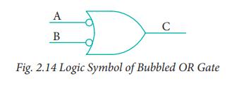
We refer this as bubbled OR gate.
The truth table for the bubbled OR is
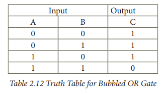
If we compare the truth tables of
the bubbled OR gate with NAND gate, they are identical. So the circuits are
interchangeable.
Therefore,

Which establishes the De Morgan's
second theorem.
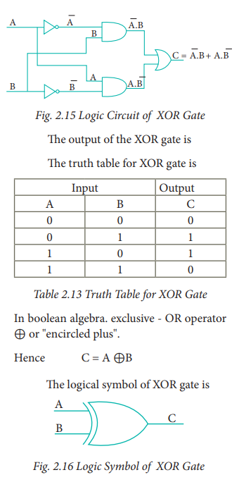
8. XOR Gate
The XOR (exclusive - OR) gate acts
in the same way as the logical "either/or." The output is
"true" if either, but not both, of the inputs are "true".
The output is "false" if both inputs are "false" or if both
inputs are "true." Another way of looking at this circuit is to
observe that the output is 1 if the inputs are different, but 0 if the inputs
are the same. The logic circuit of XOR gate is
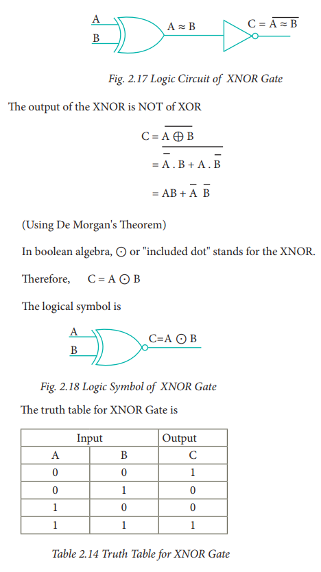
9. XNOR Gate
The XNOR (exclusive - NOR) gate is
a combination XOR gate followed by an inverter. Its output is "true"
if the inputs are the same, and "false" if the inputs are different.
In simple words, the output is 1 if the input are the same, otherwise the
output is 0. The logic circuit of XNOR gate is
Using combination of logic gates,
complex operations can be performed. In theory, there is no limit to the number
of gates that can be arranged together in a single device. But in practice,
there is a limit to the number of gates that can be packed into a given
physical space. Arrays of logic gates are found in digital integrated circuits.
Related Topics