Chapter: Software Design
Association, Aggregation and Composition Relationships
Association, Aggregation and
Composition Relationships
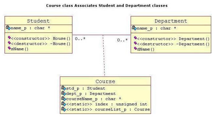
Association
It is a
simple structural connection or channel between classes and is a relationship
where all objects have their own lifecycle and there is no owner. Lets take an
example of Department and Student. Multiple students can associate with a
single Department and single student can associate with multiple Departments,
but there is no ownership between the objects and both have their own
lifecycle. Both can create and delete independently. Here is respective Model
and Code for the above example.
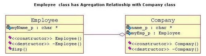
Aggregation
It is a
specialize form of Association where all object have their own lifecycle but
there is a ownership like parent and child. Child object can not belong to
another parent object at the same time. We can think of it as "has-a"
relationship. Implementation details: 1. Typically we use pointer variables
that point to an object that lives outside the scope of the aggregate class 2.
Can use reference values that point to an object that lives outside the scope
of the aggregate class 3. Not responsible for creating/destroying subclasses
Lets take an example of Employee and Company. A single Employee can not belong
to multiple Companies (legally!! ), but if we delete the Company, Employee
object will not destroy. Here is respective Model and Code for the above
example.
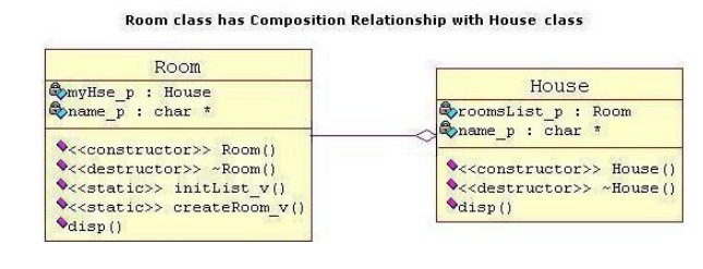
Composition
ü It is
again specialize form of Aggregation. It is a strong type of Aggregation. Here
the Parent and Child objects have coincident lifetimes. Child object dose not
have it's own lifecycle and if parent object gets deleted, then all of it's
child objects will also be deleted.
ü Implementation
details:
1. Typically
we use normal member variables
2. Can use
pointer values if the composition class automatically handles
allocation/deallocation
3. Responsible
for creation/destruction of subclasses
Lets take
an example of a relationship between House and it's Rooms. House can contain
multiple rooms there is no independent life for room and any room can not
belong to two different house. If we delete the house room will also be
automatically deleted. Here is respective Model and Code for the above example.
UML Activity Diagram
Overview:
ü Activity
diagram is another important diagram in UML to describe dynamic aspects of the
system.
ü Activity
diagram is basically a flow chart to represent the flow form one activity to
another activity. The activity can be described as an operation of the system.
ü So the
control flow is drawn from one operation to another. This flow can be
sequential, branched or concurrent. Activity diagrams deals with all type of
flow control by using different elements like fork, join etc.
Purpose:
ü The basic
purposes of activity diagrams are similar to other four diagrams. It captures
the dynamic behaviour of the system. Other four diagrams are used to show the
message flow from one object to another but activity diagram is used to show
message flow from one activity to another.
ü Activity
is a particular operation of the system. Activity diagrams are not only used
for visualizing dynamic nature of a system but they are also used to construct
the executable system by using forward and reverse engineering techniques. The only
missing thing in activity diagram is the message part.
ü It does
not show any message flow from one activity to another. Activity diagram is
some time considered as the flow chart. Although the diagrams looks like a flow
chart but it is not. It shows different flow like parallel, branched,
concurrent and single.
ü So the
purposes can be described as:
ü Draw the
activity flow of a system.
ü Describe
the sequence from one activity to another.
ü Describe
the parallel, branched and concurrent flow of the system.
How to
draw Component Diagram?
Activity
diagrams are mainly used as a flow chart consists of activities performed by
the system. But activity diagram are not exactly a flow chart as they have some
additional capabilities. These additional capabilities include branching,
parallel flow, swimlane etc.
ü Before
drawing an activity diagram we must have a clear understanding about the
elements used in activity diagram. The main element of an activity diagram is
the activity itself. An activity is a function performed by the system. After
identifying the activities we need to understand how they are associated with
constraints and conditions.
ü So before
drawing an activity diagram we should identify the following elements:
·
Activities
·
Association
·
Conditions
·
Constraints
ü Once the
above mentioned parameters are identified we need to make a mental layout of
the entire flow. This mental layout is then transformed into an activity
diagram.
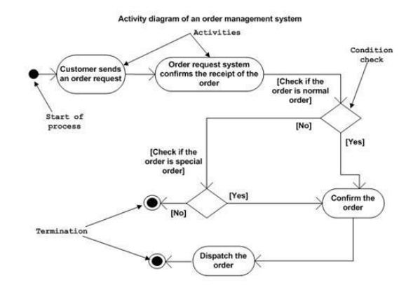
ü The
following is an example of an activity diagram for order management system. In
the diagram four activities are identified which are associated with
conditions. One important point should be clearly understood that an activity
diagram cannot be exactly matched with the code. The activity diagram is made
to understand the flow of activities and mainly used by the business users.
ü The
following diagram is drawn with the four main activities:
·
Send order by the customer
·
Receipt of the order
·
Confirm order
·
Dispatch order
After
receiving the order request condition checks are performed to check if it is
normal or special order. After the type of order is identified dispatch
activity is performed and that is marked as the termination of the process.
Where to
use Interaction Diagrams?
ü The basic
usage of activity diagram is similar to other four UML diagrams. The specific
usage is to model the control flow from one activity to another. This control
flow does not include messages.
ü The
activity diagram is suitable for modeling the activity flow of the system. An
application can have multiple systems. Activity diagram also captures these
systems and describes flow from one system to another. This specific usage is
not available in other diagrams. These systems can be database, external queues
or any other system.
ü Now we
will look into the practical applications of the activity diagram. From the
above discussion it is clear that an activity diagram is drawn from a very high
level. So it gives high level view of a system. This high level view is mainly
for business users or any other person who is not a technical person.
ü This
diagram is used to model the activities which are nothing but business
requirements. So the diagram has more impact on business understanding rather
implementation details.
ü Following
are the main usages of activity diagram:
·
Modeling work flow by using activities.
·
Modeling business requirements.
·
High level understanding of the system's
functionalities.
·
Investigate business requirements at a later stage.
Sequence Diagram
ü UML
sequence diagrams are used to represent or model the flow of messages, events
and actions between the objects or components of a system. Time is represented
in the vertical direction showing the sequence of interactions of the header
elements, which are displayed horizontally at the top of the diagram.
ü Sequence
Diagrams are used primarily to design, document and validate the architecture,
interfaces and logic of the system by describing the sequence of actions that
need to be performed to complete a task or scenario.
ü UML
sequence diagrams
ü in
sequence diagrams and when they are used. These are the diagram elements that
are supported by the Sequence Diagram
Editor tool. Some are not part of the UML are useful design tools because
they provide a dynamic view of the system behavior which can be difficult to
extract from static diagrams or specifications. Although UML sequence diagrams
are typically used to describe object-oriented software systems, they are also
extremely useful as system engineering tools to design system architectures, in
business process engineering as process flow diagrams, as message sequence
charts and call flows for telecom/wireless system design, and for protocol
stack design and analysis.
Sequence Diagram Drawing Elements
ü It
describes the basic drawing elements used specification and may not be
supported by other UML tools.
Sequence Diagram Header Elements
ü The
header portion of the sequence diagram represents the components or objects of
the system being modeled and are laid out horizontally at the top of the
diagram.
Actor
Represents
an external person or entity that interacts with the system
What can be modeled using sequence diagrams?
Sequence
diagrams are particularly useful for modeling:
Complex
interactions between components. Sequence diagrams are often used
to design the interactions between
components of a system that need to work together to accomplish a task. They
are particularly useful when the components are being developed in parallel by
different teams (typical in wireless and telephony systems) because they
support the design of robust interfaces that cover multiple scenarios and
special cases.
Use case
elaboration. Usage scenarios describe a way the system may be
used by its actors. The UML sequence
diagram can be used to flesh out the details of one or more use cases by
illustrating visually how the system will behave in a particular scenario. The
use cases along with their corresponding sequence diagrams describe the
expected behavior of the system and form a strong foundation for the
development of system architectures with robust interfaces.
Distributed
& web-based systems. When a system consists of distributed components
(such as a client communicating with
one or more servers over the Internet), sequence diagrams can be used to
document and validate the architecture, interfaces and logic of each of these
components for a set of usage scenarios.
Complex
logic. UML sequence diagrams are often used to model the logic of a complex
feature by showing the interactions
between the various objects that collaborate to implement each scenario.
Modeling multiple scenarios showing different aspects of the feature helps
developers take into account special cases during implementation.
State
machines. Telecom, wireless and embedded systems make extensive use of state
machine based designs where one or
more state machines communicate with each other and with external entities to
perform their work. For example, each task in the protocol stack of a cellular
phone goes through a series of states to perform actions such as setup a call
or register with a new base station. Similarly the call processing components
of a Mobile Switching Center use state machines to control the registration and
transfer of calls to roaming subscribers. Sequence diagrams (or call flows as
they are commonly referred to in the telecom and wireless industry) are useful
for these types of applications because they can visually depict the messages
being exchanged between the components and their associated state transitions.
Related Topics