Chapter: Computer Architecture : Arithmetic Operations
Arithmetic Operations: Multiplication
MULTIPLICATION
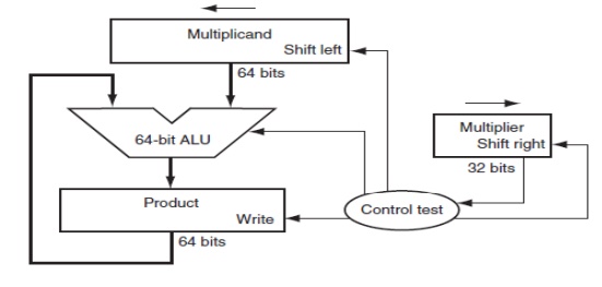
Fig. 2.3
First version of the multiplication hardware
The first operand is called the
multiplicand and the second the multiplier. The final result is called the
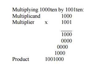
product. As you may recall, the algorithm learned in grammar school is to take
the digits of the multiplier one at a time from right to left, multiplying the
multiplicand by the single digit of the multiplier and shifting the
intermediate product one digit to the left of the earlier intermediate
products.
The first observation is that the
number of digits in the product is considerably larger than the number in
either the multiplicand or the multiplier. In fact, if we ignore the sign bits,
the length of the multiplication of an n-bit multiplicand and an m-bit
multiplier is a product that is n + m bits long. That is, n + m bits are required
to represent all possible products. Hence, like add, multiply must cope with
overflow because we frequently want a 32-bit product as the result of
multiplying two 32-bit numbers.
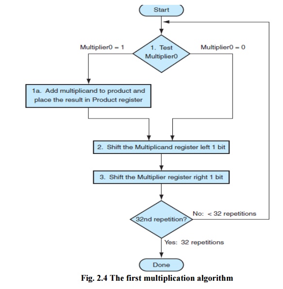
In this example we restricted the
decimal digits to 0 and 1. With only two choices, each step of the
multiplication is simple:
1. Just
place a copy of the multiplicand in the proper place if the multiplier digit is
a 1, or
2. Place 0
(0 ¥ multiplicand) in the proper place if the digit is 0.
The multiplier is in the 32-bit
Multiplier register and that the 64-bit Product register is initialized to 0.
Over 32 steps a 32-bit multiplicand would move 32 bits to the left. Hence we
need a 64-bit Multiplicand register, initialized with the 32-bit multiplicand
in the right half and 0 in the left half. This register is then shifted left 1
bit each step to align the multiplicand with the sum being accumulated in the
64-bit Product register.
Moore’s Law has
provided so much more in resources that hardware designers can now
build
a much faster multiplication hardware. Whether the multiplicand is to be added
or not is known at the beginning of the multiplication by looking at each of
the 32 multiplier bits. Faster multiplications are possible by essentially
providing one 32-bit adder for each bit of the multiplier: one input is the
multiplicand ANDed with a multiplier bit and the other is the output of a prior
adder.
SIGNED MULTIPLICATION
·
In the signed multiplication, convert the
multiplier and multiplicand to positive numbers and then remember the original
signs.
·
The algorithms should then be run for 31
iterations, leaving the signs out of the calculation
·
The shifting steps would need to extend the sign
of the product for signed numbers. When the algorithm completes, the lower word
would have the 32-bit product.
FASTER MULTIPLICATION
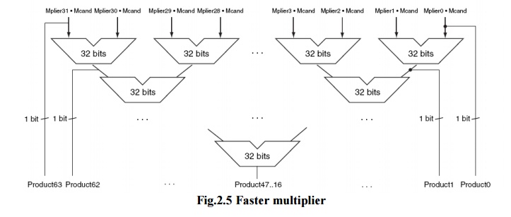
Fig.2.5
Faster multiplier
·
Faster multiplications are possible by essentially
providing one 32-bit adder for each bit of the multiplier: one input is the
multiplicand ANDed with a multiplier bit, and the other is the output of a
prior adder.
·
Connect the outputs of adders on the right to the
inputs of adders on the left, making a stack of adders 32 high.
·
The above figure shows an alternative way to
organize 32 additions in a parallel tree. Instead of waiting for 32 add times,
we wait just the log2 (32) or five 32-bit add times.
·
Multiply can go even faster than five add times
because of the use of carry save adders.
·
It is easy to pipeline such a design to be able to
support many multiplies simultaneously
Multiply in MIPS
MIPS provides a separate pair of
32-bit registers to contain the 64-bit product, called Hi and Lo. To produce a
properly signed or unsigned product, MIPS has two instructions: multiply (mult)
and multiply unsigned (multu). To fetch the integer 32-bit product, the
programmer uses move from lo (mflo). The MIPS assembler generates a
pseudoinstruction for multiply that specifies three generalpurpose registers,
generating mflo and mfhi instructions to place the product into registers.
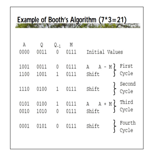
Booth Algorithm
Booth’s Algorithm Registers and Setup
• 3
n bit registers, 1 bit register logically to the right of Q (denoted as Q-1 )
• Register
set up
— Q
register <- multiplier
— Q-1 <-
0
— M
register <- multiplicand
— A
register <-
— Count <- n
• Product
will be 2n bits in A Q registers Booth’s Algorithm Control Logic
• Bits
of the multiplier are scanned one at a a time (the current bit Q0 )
• As
bit is examined the bit to the right is considered also (the previous
bit Q-1 )
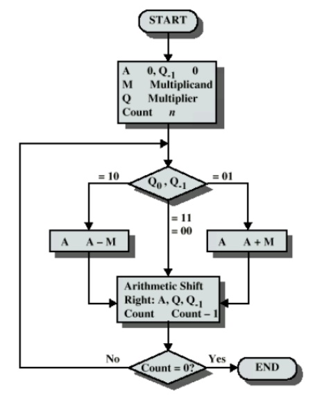
Fig. 2.6
Booth algrithm
• Then:
00:
Middle of a string of 0s, so no arithmetic operation.
01: End
of a string of 1s, so add the multiplicand to the left half of the product (A).
10:
Beginning of a string of 1s, so subtract the
multiplicand from the left half of the product (A).
11:
Middle of a string of 1s, so no arithmetic
operation.
• Then
shift A, Q, bit Q-1 right one bit using an arithmetic shift
• In
an arithmetic shift, the msb remains
Related Topics