Chapter: Fundamentals of Database Systems : Databases and Database Users
An Example - Databases and Database Users
An Example
Let us consider a simple example that most readers may be familiar with:
a UNIVERSITY
database for maintaining information concerning
students, courses,
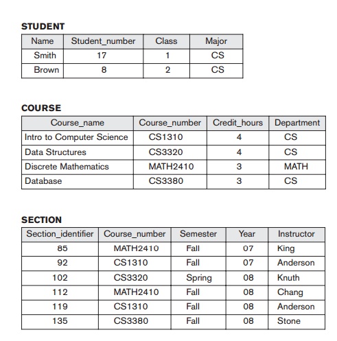
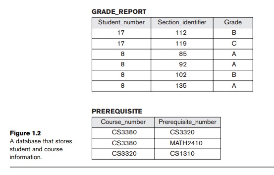
and grades in a university environment. Figure 1.2
shows the database structure and a few sample data for such a database. The
database is organized as five files, each of which stores data records of the same type.3 The STUDENT file stores data on each student, the COURSE file
stores data on each course, the SECTION file
stores data on each section of a course, the GRADE_REPORT file
stores the grades that students receive in the various sections they have
completed, and the PREREQUISITE file stores the prerequisites of
each course.
To define this database, we
must specify the structure of the records of each file by specifying the
different types of data elements to
be stored in each record. In Figure 1.2, each STUDENT record
includes data to represent the student’s Name, Student_number,
Class (such as freshman or ‘1’,
sophomore or ‘2’, and so forth), and

(such as mathematics or ‘MATH’ and computer science or ‘CS’); each COURSE record includes data to represent the Course_name, Course_number, Credit_hours, and Department (the department that offers the course); and so on. We must also specify a data type for each data element within a record. For example, we can specify that Name of STUDENT is a string of alphabetic characters, Student_number of STUDENT is an integer, and Grade of GRADE_REPORT is a single character from the set {‘A’, ‘B’, ‘C’, ‘D’, ‘F’, ‘I’}. We may also use a coding scheme to rep-resent the values of a data item. For example, in Figure 1.2 we represent the Class of a STUDENT as 1 for freshman, 2 for sophomore, 3 for junior, 4 for senior, and 5 for graduate student.
To construct the UNIVERSITY database, we store data to represent each student, course, section,
grade report, and prerequisite as a record in the appropriate file. Notice that
records in the various files may be related. For example, the record for Smith in the
STUDENT file is related to two records in
the
GRADE_REPORT file that specify Smith’s grades in two sections. Similarly, each record in the PREREQUISITE file relates two course records: one representing the course and the other
represent-ing the prerequisite. Most medium-size and large databases include
many types of records and have many
relationships among the records.


Database manipulation involves
querying and updating. Examples of queries are as follows:
Retrieve the transcript—a list of
all courses and grades—of ‘Smith’
List the names of students who
took the section of the ‘Database’ course offered in fall 2008 and their grades
in that section
List the prerequisites of the
‘Database’ course
Examples of updates include the following:
Change the class of ‘Smith’ to
sophomore
Create a new section for the
‘Database’ course for this semester
Enter a grade of ‘A’ for ‘Smith’
in the ‘Database’ section of last semester
These informal queries and updates must be specified precisely in the
query lan-guage of the DBMS before they can be processed.
At this stage, it is useful to describe the database as a part of a
larger undertaking known as an information system within any organization. The
Information Technology (IT) department within a company designs and maintains
an informa-tion system consisting of various computers, storage systems,
application software, and databases. Design of a new application for an
existing database or design of a brand new database starts off with a phase
called requirements specification and
analysis. These requirements are
documented in detail and transformed into a
conceptual design that can be represented and manipulated using some
computer-ized tools so that it can be easily maintained, modified, and
transformed into a data-base implementation. (We will introduce a model called
the Entity-Relationship model in Chapter 7 that is used for this purpose.) The
design is then translated to a logical
design that can be expressed in a data model implemented in a commercial DBMS. (In this book we will emphasize
a data model known as the Relational Data Model from Chapter 3 onward. This is
currently the most popular approach for designing and implementing databases
using relational DBMSs.) The final stage is physical design, during which further specifications are provided
for storing and accessing the
database. The database design is implemented, populated with actual data, and
continuously maintained to reflect the state of the miniworld.
Related Topics