Chapter: Civil : Railway Airport Harbour Engineering : Railway Engineering : Signalling and Interlocking
Various Types of Fixed Signals used on railways
Fixed Signals
The various types of fixed signals used on railways are as
follows.
Semaphore signals
The word 'semaphore' was first
used by a Greek historian. 'Sema' means sign and 'phor' means to bear. A
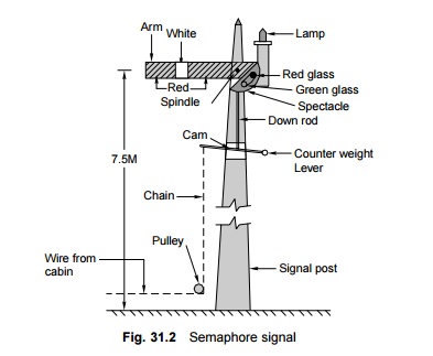
semaphore signal consists of a movable arm pivoted on a vertical post through a
horizontal pin as shown in Fig. 31.2.

The arm of the semaphore signal
on the side facing the driver is painted red with a vertical white stripe. The
other side of the signal is painted white with a black vertical stripe. The
complete mechanical assembly of the signal consists of an arm, a pivot, a
counterweight spring stop, etc., and is housed on top of a tubular or lattice
post. In order for the signal to also be visible at night, a kerosene oil or
electric lamp, operated through a twilight switch, is fixed to the post. A
spectacle is also attached to the moving signal arm, which contains green and
red coloured glasses. The red glass is positioned at the upper end and the
green glass is positioned at the lower end of the spectacle so that the red
light is visible to the driver when the arm is horizontal and the green light
is visible when the arm is lowered. The semaphore signal can be used as a stop
signal as well as a warner signal.
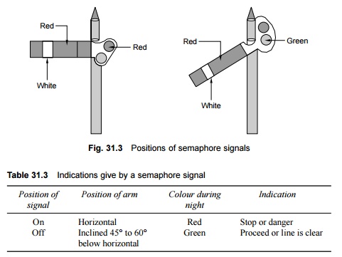
With reference to lower quadrant
signalling, the colour aspects of a semaphore signal and their corresponding
indications when the arm of the signal is in two distinct positions are shown
in Fig. 31.3 and also Table 31.3.
Lower quadrant semaphore signals
move only in the fourth quadrant of a circle and have only two colour aspects.
In order to provide the drivers with further information, upper quadrant
signalling is sometimes used on busy routes. In this system, the arms of the
semaphore signals rest in three positions and the signals have three colour aspects,
namely, red, yellow, and green associated with the horizontal, 45 o above
horizontal, and vertical directions, respectively.
The signals are designed to be
fail-safe so that if there is any failure in the working of the equipment, they
will always be in the stop position. These signals are operated by hand levers
or buttons located in a central cabin, which is normally provided near the
station master's office. Semaphore signals are normally provided as outer
signals, home signals, starter signals, advanced starter signals, and warner
signals.
Permissive signal-warner or distant
signal
In order to ensure that trains
speed up safely, it is considered necessary that warning be given to drivers
before they approach a stop signal. This advance warning is considered
necessary, otherwise the drivers may confront a 'stop signal' when they least
expect it and take abrupt action, which can lead to perilous situations. A
warner or distant signal has, therefore, been developed, which is to be used
ahead of a stop signal and is in the form of a permissive signal that can be
passed even in most restricted conditions. In the case of a stop signal, the
driver has to stop the train when it is in the 'on' position, but in the case
of a permissive signal, the driver can pass through even when it is in the 'on'
position. The most restrictive aspect of a permissive or warner signal is that
the driver is not supposed to stop at the signal even when it is in the 'on'
position.
The warner signal is similar to a
stop signal except that the movable arm is given the shape of fish tail by
providing a V-shaped notch at the free end; the white strip is also V-shaped.
In the case of signalling using
coloured light, the permissive signal is distinguished from the stop signal by
the provision of a P marker disc on the signal post.
The warner signal is intended to
warn the driver of a train regarding the following aspects as explained in
Table 31.4.
(a) That the
driver is approaching a stop signal.
(b) To inform
the diver as to whether the approach signal is in an 'on' or 'off' position.
Table 31.4 Position of warner arm
or distant signal
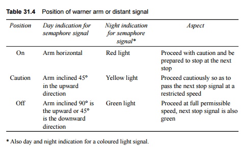
* Also day and night indication for a coloured light signal.
The
warner signal can be placed at either one of the following locations.
(a) Independently
on a post with a fixed green light 1.5 m to 2 m above it for night indication.
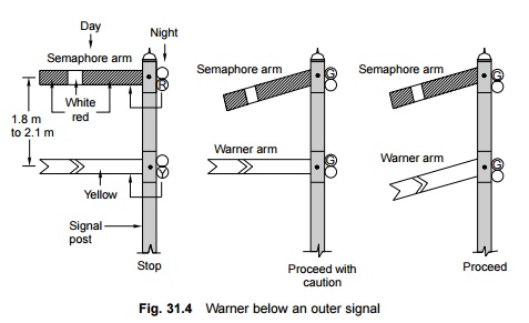
(b) On the
same post below the outer signal or the home signal.
In case a warner is fixed below
an outer signal the various positions of the outer and warner signals and their
corresponding indications are given in Fig. 31.4.
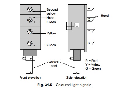
Coloured light signals
These signals use coloured lights
to indicate track conditions to the driver both during the day and the night.
In order to ensure good visibility of these light signals, particularly during
daytime, the light emission of an electric 12-V, 33-W lamp is passed through a
combination of lenses in such a way that a parallel beam of focused light is
emitted out. This light is protected by special lenses and hoods and can be
distinctly seen even in the brightest sunlight. The lights are fixed on a
vertical post in such a way that they are in line with the driver's eye level.
The system of interlocking is so arranged that only one aspect is displayed at
a time. Coloured light signals are normally used in suburban sections and
sections with a high traffic density. Coloured light signals can be of the
following types.
a) Two-aspect,
namely, green and red
b) Three-aspect,
namely, green, yellow, and red
c) Four-aspect,
namely, green, yellow (twice), and red.
In India, mostly three-aspect or four-aspect coloured light
signalling is used. In the case of three-aspect signalling, green, yellow, and
red lights are used. Green indicates 'proceed', yellow indicates 'proceed with
caution', and red indicates 'stop' (Fig. 31.5).
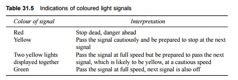
In the case of four-aspect coloured light signalling, the
interpretation of the colours are given in Table 31.5.
Table 31.5 Indications of coloured
light signals
In conventional semaphore
signals, the 'on' position is the normal position of the signal and the signals
are lowered to the 'off' position only when a train is due. In the case of
coloured light signals placed in territories with automatic signalling, the
signal is always green or in the 'proceed' position. As soon as a train enters
a section, the signal changes to 'Red' or the 'stop' position, which is
controlled automatically by the passage of the train itself. As the train
passes through the block section, the signal turns yellow to instruct the
driver to 'proceed with caution' and, finally, when the train moves onto the
next block section, the signal turns green indicating to the driver to 'proceed
at full permissible speed'.
Thus it can be seen that each
aspect of the signal gives two pieces of information to the driver. The first
is about the signal itself and the second is about the condition of the track
ahead or of the next signal. This helps the driver to manoeuvre the train
safely and with confidence even at the maximum permissible speed.
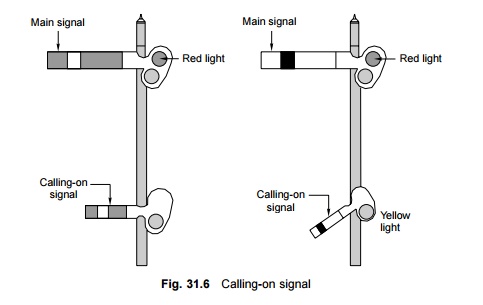
Calling-on signal
This consists of a small arm
fixed on a home signal post below the main semaphore arm (Fig. 31.6). When the
main home signal is in the horizontal (on) position and the calling-on signal
is in on inclined (off) position, it indicates that the train is permitted to
proceed cautiously on the line till it comes across the next stop signal. Thus
the calling-on signal is meant to 'call' the train, which is waiting beyond the
home signal.
The calling-on signal is useful
when the main signal fails, and in order to receive a train, an authority
letter has to be sent to the driver of the waiting train to instruct him/her to
proceed to the station against what is indicated by the signal. In big stations
and yards, the stop signals may be situated far off from the cabin and the
calling-on signal expedites the quick reception of the train even the when
signal is defective.
Co-acting signal
In case a signal is not visible
to the driver due to the presence of some obstruction such as an overbridge or
a high structure, another signal is used in its place, preferably on the same
post. This signal, known as the co-acting signal, is an exact replica of the
original signal and works in unison with it.
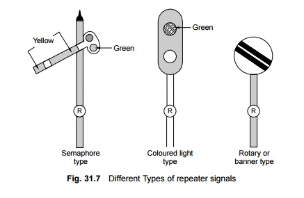
Repeater signal
In cases where a signal is not
visible to the driver from an adequate distance due to sharp curvature or any
other reason or where the signal is not visible to the guard of the train from
his position at the rear end of a platform, a repeater signal is provided at a
suitable position at the rear of the main signal. A repeater signal is provided
with an R marker and can be of the following types.
(a) A
square-ended semaphore arm with a yellow background and a black vertical band.
(b) A coloured
light repeater signal.
(c) A rotary
or disc banner type signal.
The 'off' positions of these
three types of repeater signals are depicted in Fig. 31.7.
Shunt signals
These are miniature signals and
are mostly used for regulating the shunting of vehicles in station yards.
Unlike fixed signals, these are small in size and are placed on an independent
post of a running signal post. In semaphore signalling areas, the shunt signals
are of the disc type.
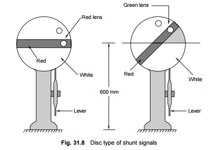
The disc type of shunt signal consists
of a circular disc with a red band on a white background. The disc revolves a
round a pivot and is provided with two holes, one for the red lamp and the
other for the green lamp, for the purpose of night indication. At night, the
'on' position of the signal is indicated by the horizontal red band and the red
light, indicating danger. During the day the red band inclined to the
horizontal plane and during the night the green light indicate that the signal
is 'off' (Fig. 31.8).
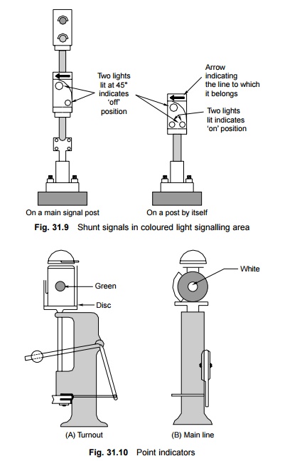
In colour light signalling areas, the shunt signal
on an independent post consists of two white lights forming a line parallel to
the horizontal plane. This indicates that the signal is 'on' or that there is
danger ahead whereas two white lights forming a line inclined to the horizontal
plane indicate 'off' or that the train can proceed (Fig. 31.9).
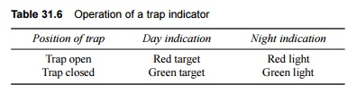
Point indicators
These are used to indicate
whether points have been set for the main line or turnout side (Fig. 31.10). It
essentially consists of an open box with two white circular discs forming two
opposite sides of the box and green bands on the other two remaining sides. The
box rotates automatically about a vertical axis with the movement of the
points. The white disc indicates that the points are set for the main line.
When the points are set for the turnout side, the green bands are visible. At
night white light indicates a main line setting and green light signifies a
turnout side setting.
Trap indicator
A trap is a device fitted on the
track, which in its open position derails the vehicle that passes over it. When
the trap is closed, the vehicle passes over it as it would over a normal track.
A trap indicator reveals whether the trap is in an 'open' or 'closed' position.
The details of the same are given in Table 31.6.
Caution indicators
When the track is undergoing
repair, trains are required to proceed with caution at restricted speeds and
may even have to stop. Caution indicators help the driver of a train to reduce
the speed of (or even stop) the train at the affected portion of the track and
then return it to the normal speed once that portion has been covered. The
following indicators are used for this purpose.
Caution indicator This
cautions the driver to get ready to reduce the speed. Speed indicator The
driver has to reduce the speed (or stop) at this location. Stop indicator or
stop board The driver has to stop the train at this location.
Termination indicator This
indicates that the driver can assume normal speed and that the speed
restriction zone has ended.
These indicators are also called
temporary fixed engineering signals and are provided in the direction of the
approaching train in the case of double lines and in both directions in the
case of single lines.
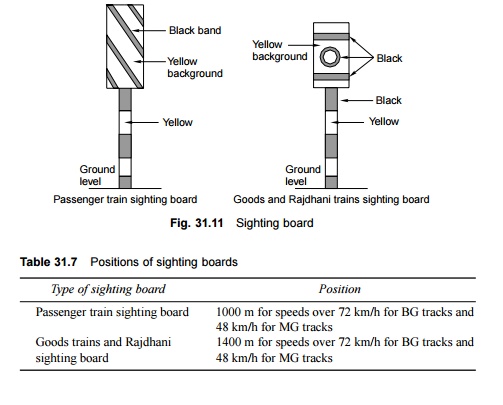
Sighting board
A sighting board (Fig. 31.11) is
an indication to the driver that he or she is approaching the first stop signal
of a railway station. The function of a sighting board is to allow the driver
to estimate the location of the next stop signal from the current location so
that he/she starts applying brakes in case the first stop signal is in an 'on'
position. As the requisite braking distance of goods trains and Rajdhani trains
is greater than that of the passenger trains, the sighting boards for goods
trains and Rajdhani trains are located farther and their design is different
from that of sighting boards meant for passenger trains. The distances of
sighting boards are listed in Table 31.7.
Related Topics