Chapter: Electrical Engineering and Instrumentation : DC Machines
Three Phase Circuits, A Review
Three Phase Circuits, A Review
Polyphase System
Circuit or system in which AC sources operate at the same frequency but different phases are known as polyphase.
Two Phase System
A generator consists of two coils placed perpendicular to each other. The voltage generated by one lags the other by 90°.
Three Phase System
A generator consists of three coils placed 120° apart. The voltage generated are equal in magnitude but, out of phase by 120°. Three phase is the most economical polyphase system.
Importance of Three Phase System
Uniform power transmission and less vibration of three phase machines.
The instantaneous power in a 3f system can be constant (not pulsating).
High power motors prefer a steady torque especially one created by a rotating magnetic field.
Three phase system is more economical than the single phase. The amount of wire required for a three phase system is less than required for an equivalent single phase system.
Three Phase Generation
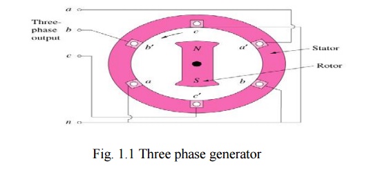
Working
The generator consists of a rotating magnet (rotor) surrounded by a stationary winding (stator).
Three separate windings or coils with terminals a-a’, b-b’, and c-c’ are physically placed 120° apart around the stator.
As the rotor rotates, its magnetic field cuts the flux from the three coils and induces voltages in the coils.
The induced voltage have equal magnitude but out of phase by 120°.
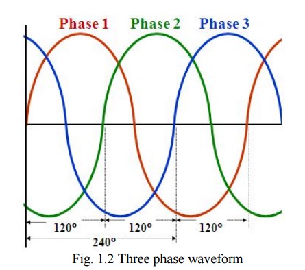
Three-Phase Waveform
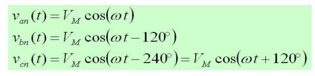
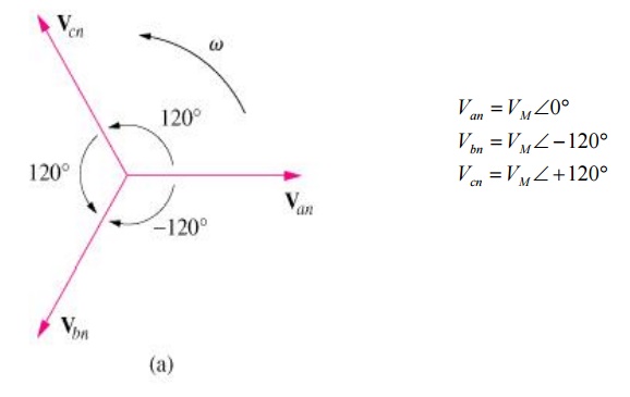
Three Phase Quantities
Balanced 3f Voltages
Balanced three phase voltages:
Same magnitude (VM )
120° phase shift
Balanced 3f Currents
Balanced three phase currents:
Same magnitude (IM )
120° phase shift

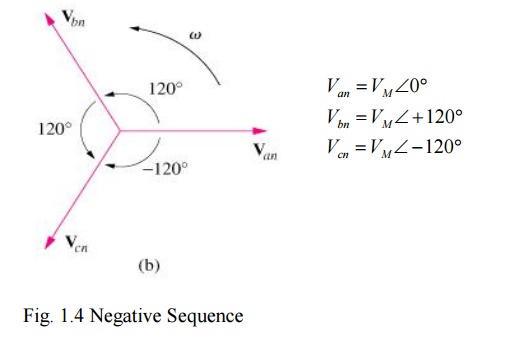
Phase Sequence
Positive Sequence
Negative Sequence
POWER
The instantaneous power is constant.
p(t)= pa(t)+pb(t)+ pc(t)
= 3 [VMIM /2] cos(q)
= 3VrmsIrmscos(q )
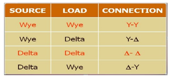
Three Phase Connection
Source-Load Connection
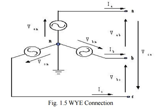
WYE Connection
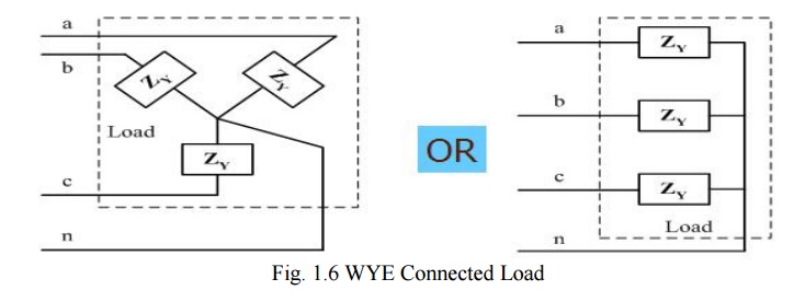
WYE Connected Load
Balanced Y-Y Connection
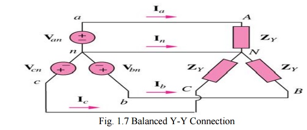
Phase Currents and Line Currents
In Y-Y system, line current is equal to phase current, IL = IP
Delta Connection
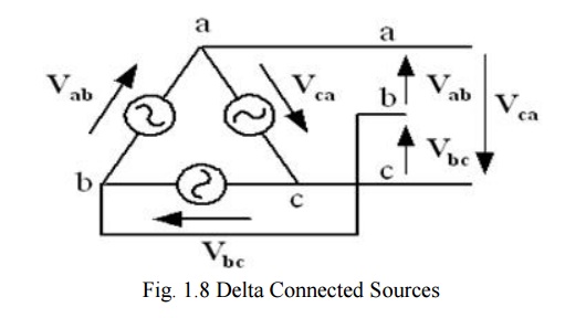
Delta Connected Sources
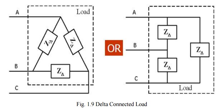
DELTA Connected Load
Balanced D- D Connection
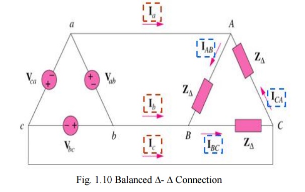
PHASE VOLTAGE AND LINE VOLTAGE
In D-D system, line voltages are equal to phase voltages: VL = VP
Power Measurement in a Three Phase Circuit Using Two-Wattmeter Method
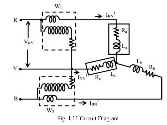
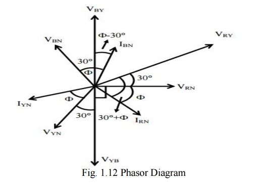
Phasor Diagram
The reading of the first wattmeter is,

The reading of the second wattmeter is,

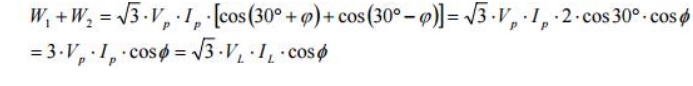
The sum of the two wattmeter readings is,
The difference of the two wattmeter readings is,
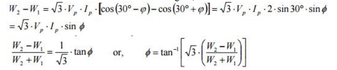
Power factor (cosф) can be determined using the above expression.
Related Topics