Chapter: Electrical and electronics : Circuit Theory : Network Reduction and Network Theorems for DC And AC Circuits
Thevenins Theorem
THEVENINS THEOREM:
In circuit theory, Thévenin's theorem for linear electrical networks states that any combination of voltage sources, current sources, and resistors with two terminals is electrically equivalent to a single voltage source V and a single series resistor R. For single frequency AC systems the theorem can also be applied to general impedances, not just resistors.
The procedure adopted when using Théveni determine the current in any branch of an active network (i.e. one containing a source of e.m.f.):
(i) remove the resistance R from that branch,
(ii) determine the open-circuit voltage, E, across the break,
remove each source of e.m.f. and replace them by their internal resistances and then determine the resistance, r, ‘looking-in’break.
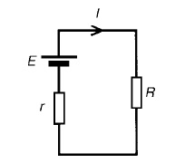
(iv) determine the value of the current from the equivalent circuit shown in Figure 13.33, i.e. I = ER+r
Problem 1: Use Thévenin’s theorem to find the current flowing in the 10 Ω resistor for the circuit shown in Figure
Following the above procedure:
The 10 Ωresistance is removed from the circuit as shown in Figure There is no current flowing in the 5 Ωresistor and current I1 is given by:
I1 = 10/R1 + R2
= 10/2 + 8
= 1A
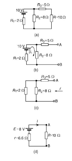
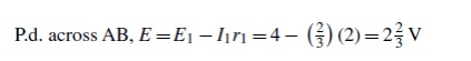
P.d. across R2 =I1R2 =1×8=8V Hence p.d. across AB, i.e. the open-circuit voltage across the break, E =8V
(iii) Removing the source of e.m.f. gives the circuit of Figure Resistance, r = R3 + R1R2/R1 + R2
=5+ (2×8/2+8)
= 5 + 1.6 = 6.6 Ω
(iv) The equivalent Thévenin’s circuit is shown in F
Current I = E/R+r= 8/10+6.6= 8/16.6=0.482A
Problem 2: For the network shown in Figure determine the current in the 0.8 Ω resistor using
Thévenin’s theorem.
Following the procedure:
The 0.8_ resistor is removed from the circuit as shown in Figure
Current I1 = 12/1+5+4= 12/10
=1.2A
P.d. across 4 Ωresistor=4I1 =(4) (1.2)=4.8V
Hence p.d. across AB, i.e. the open-circuit voltage across AB, E =4.8V
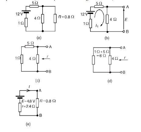
(iii) Removing the source of e.m.f. gives the circuit shown in Figure (c). The equivalent circuit of Figure
(c) is shown in Figure (d), from which,resistance r = 4×6/4+6= 24/10
=2.4 Ω
(iv) The equivalent Thévenin’s circuit I=E/+R is show
= 4.8/2.4+0.8
= 4.8/3.2
I = 1.5A=current in the 0.8 Ωresistor
Problem 3: U Use Thévenin’s theorem to determine the current I flowing in the 4 Ω resistor shown in Figure.
Find also the power dissipated in the 4 Ωresistor.
(i) The 4 Ωresistor is removed from the circuit as shown in Figure
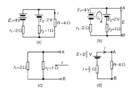
(ii) Current I1 = E1 −E2/r1 +r2
= 4−2/2+1
= 2/3A
(iii) Removing the sources of e.m.f. gives the circuit shown in Figure (c), from which resistance
r = 2 × 1/2 + 1 = 2/3 Ω
(iv)The equivalent Thévenin’s circuit is show
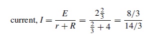
= 8/14
= 0.571A
= current in the 4 Ωresistor
Problem 4: Power dissipated in 4 Ωresistor,P=I2R=(0.571)2 (4)=1.304W Use Thévenin’s t to determine the current flowing in the 3 Ω resistance of the network shown in Figure (a). The
voltage source has negligible internal resistance.
i) The 3 Ωresistance is removed from the circuit as shown in Figure (b).
(ii) The 1 2/3 Ωresistance now carries no current. P.d. across 10 Ωresistor=(10/10+5)(24)
=16V
Hence p.d. across AB, E =16V
(iii) Removing the source of e.m.f. and replacing it by its internal resistance means that the 20 Ωresistance is short-circuited as shown in Figure (c) since its internal resistance is zero. The 20 Ωresistance may thus be removed as shown in Figure (d)
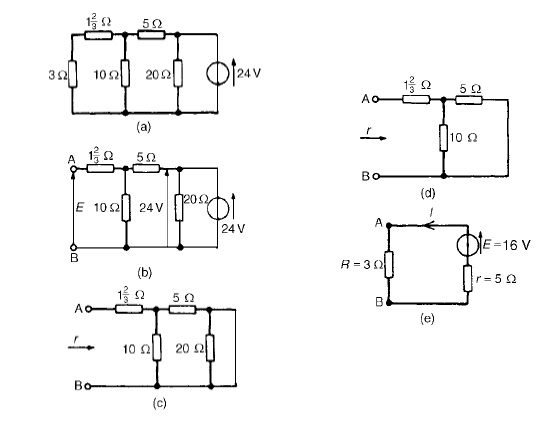
From Figure (d), resistance,
r =1 2/3+ 10×5/10+5 =5 Ω
(iv) The equivalent Thévenin’s circuit is show current, I = E/r +R= 16/3+5= 16/8
=2A
Problem 5: AWheatstone Bridge network is shown in Figure (a). Calculate the current flowing in the 32 Ωresistor, and its direction, using Théveni negligible resistance.
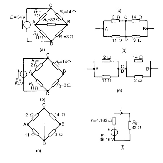
The 32 Ωresistor is removed from the circuit as shown in Figure (b) The p.d. between A and C,
VAC =R1/R1 +R4 (E) =2/2+11(54) = 8.31V The p.d. between B and C,
VBC =R2/R2 +R3 (E) =14/14+3(54) = 44.47V Hence the p.d. between A and B=44.47−8.31=36.16V
Point C is at a potential of +54V. Between C and A is a voltage drop of 8.31V. Hence the voltage at point A is 54−8.31=45.69V. Between C and B is a voltage drop of 44.47V. Hence the voltage at point B is 54−44.47=9.53V. Since the voltage at A is greater than at B, current must flow in the direction A to B.
Replacing the source of e.m.f. with a short-circuit (i.e. zero internal resistance) gives the circuit shown in Figure (c). The circuit is redrawn and simplified as shown in Figure (d) and (e), from which the resistance between terminals A and B,
r = 2 × 11/2 + 11+ 14 × 3/14 + 3
= 22/13+ 42/17
= 1.692 + 2.471 = 4.163 Ω
(iv) The equivalent Thévenin’s circuit is show
current I = E/r +R5
= 36.16/4.163+32 =1A
Related Topics