Chapter: High Voltage Engineering : High Voltage Testing of Electrical Power Apparatus
The basic PD(Partial Discharge) test circuit
The basic PD(Partial Discharge) test circuit
Electrical
PD detection methods are based on the appearance of a 'PD (current or voltage)
pulse‘ at the terminals of a test object, which may be either a simple
dielectric test specimen for fundamental investigations or even a largeh.v.
apparatus which has to undergo a PD test. For the evaluation of the fundamental
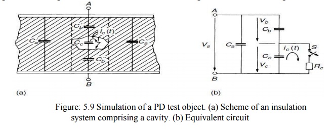
quantities related to a PD pulse we simulate the test object, as usual, by the
simple capacitor arrangement as shown in Fig.5.9(a), comprising solid orfluid
dielectric materials between the two electrodes or terminals A and B, and a
gas-filled cavity. The electric field distribution within this test object is
here simulated by some partial capacitances, which is possible as long as no
space charges disturb this distribution. discharge current which cannot be measured,
would have a shape as governed by the gas discharge process and would in
general be similar to a Dirac function, i.e. this discharge current is
generally a very short pulse in the nanosecond range. Let us now assume that
the sample was charged to the voltage Va but the terminals A, B are no longer
connected to a voltage source.
If the
switch Sis closed and Cc becomes completely discharged, the current i releases
charge υqc D Ccυ Vc from Cc, a charge which is lost in the whole system
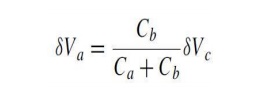
asassumed for simulation. By comparing the charges within the system before and
after this discharge, we receive the voltage drop across the terminal υVa as
This voltage drop contains no information about the charge υqc, but it is
proportional to Cbυ Vc, a magnitude vaguely related to this charge, as Cbwill
increase with the geometric dimensions of the cavity. Va is clearly a quantity
which could be measured.
It is a
negative voltage step with a rise time depending upon the duration of ic. The
magnitude of the voltage step, however, is quite small, although υVc is in
a range of some102 to 103 V; but the ratio Cb/Ca will always be very small and
unknown according to eqn. Thus a direct detection of this voltage step by
measurement of the whole input voltage would be a tedious task. The detection
circuits are therefore based upon another quantity, which can immediately be
derived from a nearly complete circuit shown in Fig. 5.10.
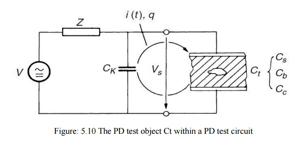
The test
object, Fig. 5.9 (a), is now connected to a voltage source V, in general an
a.c. power supply. An impedance Z, comprising either only the natural impedance
of the lead between voltage source and the parallel arrangement of CK and
enlarged by a PD-free inductance or filter, may disconnect the 'coupling
capacitor‘ CK and the test specimen Ct from the voltage source during the short
duration PD phenomena only. Then CK is a storage capacitoror quite a stable
voltage source during the short period of the partial discharge. It releases a
charging current or the actual 'PD current pulse‘ i between CK and Ct and tries
to cancel the voltage drop υVa across υVa is completely compensated and the
charge transfer provided by the current pulse i is given by
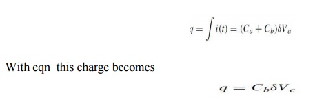
and is
the so-called apparent charge of a PD pulse, which is the most fundamental
quantity of all PD measurements. The word ‗apparent‘ was introduced because
this charge again is not equal to the amount of charge locally involved at the
site of the discharge or cavity Cc. This PD quantity is much more realistic
than Va in eqn as the capacitance Ca of the test object, which is its main part
of Ct, has no influence on it. And even the amount of charge as locally
involved during a discharge process is of minor interest, as only the number
and magnitude of their dipole moments and their interaction with the electrodes
or terminals determine the magnitude of the PD current pulse. The condition CK × Ca_.DCt
is, however, not always applicable in practice, as either Ct is quite large, or
the loading of an a.c. power supply becomes high and the cost of building such
a large capacitor, which must be free of anyPD, is not economical.
For a
finite value of CK the charge q or the current is reduced, as the voltage
across CK will also drop during the charge transfer. Designating this voltage
drop by υVŁa, we
may compute this value by assuming that the same charge Cb, Vc has to be
transferred in the circuits of Figs 5.9(b) and 5.10 . Therefore The
relationship qm/q indicates the difficulties arising in PD measurements for
test objects of large capacitance values Ct. Although CK and Ct may be known,
the ability to detect small values of q will decrease as all instruments
capable of integrating the currents i will have a lower limit for quantifying.
Equation
therefore sets limits for the recording of ‗pi co coulombs‘ in large test
objects.
During
actual measurements, however, a calibration procedure is needed during which
artificial apparent charge q of well-known magnitude is injected to the test
object, critical note is made with reference to the definition of the apparent
charge q as given in the new IEC Standard 60270.31 The original text of this
definition is: apparent charge q of a PD pulse is that unipolar. charge which,
if injected within a very short time between the terminals of the test object in
a specified test circuit, would give the same reading on the measuring
instrument as the PD current pulse itself. The apparent charge is usually
expressed inpicocoulombs.
This
definition ends with:
NOTE –
The apparent charge is not equal to the amount of charge locallyinvolved at the
site of the discharge and which cannot be measured directly. This definition is
an indication of the difficulties in understanding the physical phenomena
related to a PD event. As one of the authors of this book has been chairman of
the International Working Group responsible for setting up this new standard,
he is familiar with these difficulties and can confirm that the definition is
clearly a compromise which could be accepted by the international members of
the relevant Technical Committee of IEC. The definition is correct. It relates
to a calibration procedure of a PD test and measuring circuit, as already
mentioned above. The ‗NOTE‘, however, is still supporting the basically wrong
assumption that a certain amount or number of charges at the site of the
discharge should be measured. As already mentioned: it is not the number of
charges producing the PD currents, but the number of induced dipole moments
which produce a sudden increase in the capacitance of the test object.
Related Topics