Chapter: Fundamentals of Database Systems : Conceptual Modeling and Database Design : Practical Database Design Methodology and Use of UML Diagrams
The Database Design and Implementation Process: Phase 2: Conceptual Database Design
Phase 2: Conceptual Database Design
The second phase of database design involves two parallel activities. The first activity, conceptual schema design, examines the
data requirements resulting from Phase 1 and produces a conceptual database
schema. The second activity, transaction
and application design, examines the database applications analyzed in Phase 1 and produces high-level
specifications for these applications.
Phase 2a: Conceptual Schema
Design. The conceptual schema produced by this phase is usually contained in a DBMS-independent high-level data
model for the following reasons:
The goal of conceptual schema design is a complete understanding of the
database structure, meaning (semantics), interrelationships, and constraints.
This is best achieved independently of a specific DBMS because each DBMS
typically has idiosyncrasies and restrictions that should not be allowed to
influence the conceptual schema design.
The conceptual schema is invaluable
as a stable description of the
database contents. The choice of DBMS and later design decisions may change
with-out changing the DBMS-independent conceptual schema.
A good understanding of the
conceptual schema is crucial for database users and application designers. Use
of a high-level data model that is more expressive and general than the data
models of individual DBMSs is there-fore quite important.
The diagrammatic description of
the conceptual schema can serve as a vehicle of communication among database
users, designers, and analysts. Because high-level data models usually rely on
concepts that are easier to understand than lower-level DBMS-specific data
models, or syntactic defini-tions of data, any communication concerning the
schema design becomes more exact and more straightforward.
In this phase of database design, it is important to use a conceptual
high-level data model with the following characteristics:
Expressiveness. The data model should be
expressive enough to distin-guish different types of data, relationships, and
constraints.
Simplicity and understandability. The model
should be simple enough for typical
nonspecialist users to understand and use its concepts.
Minimality. The model should have a small
number of basic concepts that are
distinct and nonoverlapping in meaning.
Diagrammatic representation. The model
should have a diagrammatic notation
for displaying a conceptual schema that is easy to interpret.
Formality. A conceptual schema expressed in
the data model must repre-sent a formal unambiguous specification of the data.
Hence, the model con-cepts must be defined accurately and unambiguously.
Some of these requirements—the first one in particular—sometimes
conflict with the other requirements. Many high-level conceptual models have
been proposed for database design (see the Selected Bibliography in Chapter 8).
In the following dis-cussion, we will use the terminology of the Enhanced
Entity-Relationship (EER) model presented in Chapter 8 and we will assume that
it is being used in this phase. Conceptual schema design, including data
modeling, is becoming an integral part of object-oriented analysis and design
methodologies. The UML has class diagrams that are largely based on extensions
of the EER model.
Approaches to Conceptual
Schema Design. For conceptual schema design, we
must identify the basic components (or constructs) of the schema: the entity
types, relationship types, and attributes. We should also specify key
attributes, cardinality and participation constraints on relationships, weak
entity types, and specialization/ generalization hierarchies/lattices. There
are two approaches to designing the conceptual schema, which is derived from
the requirements collected during Phase 1.
The first approach is the centralized
(or one shot) schema design approach, in which the requirements of the different
applications and user groups from Phase 1 are merged into a single set of
requirements before schema design begins. A single schema corresponding to the
merged set of requirements is then designed. When many users and applications
exist, merging all the requirements can be an arduous and time-consuming task.
The assumption is that a centralized authority, the DBA, is responsible for
deciding how to merge the requirements and for designing the conceptual schema
for the whole database. Once the conceptual schema is designed and finalized,
external schemas for the various user groups and applications can be specified
by the DBA.
The second approach is the view
integration approach, in which the requirements are not merged. Rather a
schema (or view) is designed for each user group or application based only on
its own requirements. Thus we develop one high-level schema (view) for each
such user group or application. During a subsequent view integra-tion phase, these schemas are merged or integrated
into a global conceptual schema for
the entire database. The individual views can be reconstructed as external
schemas after view integration.
The main difference between the two approaches lies in the manner and
stage in which multiple views or requirements of the many users and
applications are recon-ciled and merged. In the centralized approach, the
reconciliation is done manually by the DBA staff prior to designing any schemas
and is applied directly to the require-ments collected in Phase 1. This places
the burden to reconcile the differences and conflicts among user groups on the
DBA staff. The problem has been typically dealt with by using external
consultants/design experts, who apply their specific methods for resolving
these conflicts. Because of the difficulties of managing this task, the view
integration approach has been proposed as an alternative technique.
In the view integration approach, each user group or application
actually designs its own conceptual (EER) schema from its requirements, with
assistance from the DBA staff. Then an integration process is applied to these
schemas (views) by the DBA to form the global integrated schema. Although view
integration can be done manu-ally, its application to a large database
involving dozens of user groups requires a methodology and the use of automated
tools. The correspondences among the attributes, entity types, and relationship
types in various views must be specified before the integration can be applied.
Additionally, problems such as integrating conflicting views and verifying the
consistency of the specified interschema correspondences must be dealt with.
Strategies for Schema
Design. Given a set of requirements, whether
for a single user
or for a large user community, we must create a
conceptual schema that satisfies these requirements. There are various
strategies for designing such a schema. Most strategies follow an incremental
approach—that is, they start with some important schema constructs derived from
the requirements and then they incrementally mod-ify, refine, and build on
them. We now discuss some of these strategies:
Top-down strategy. We start with a schema containing high-level abstractions and then apply
successive top-down refinements. For example, we may specify only a few
high-level entity types and then, as we specify their attributes, split them
into lower-level entity types and specify the relationships. The process of
specialization to refine an entity type into subclasses that we illustrated in
Sections 8.2 and 8.3 (see Figures 8.1, 8.4, and 8.5) is another activity during
a top-down design strategy.
Bottom-up strategy. Start with a schema containing
basic abstractions and then combine
or add to these abstractions. For example, we may start with the database
attributes and group these into entity types and relationships. We may add new
relationships among entity types as the design progresses. The process of
generalizing entity types into higher-level generalized super-classes (see
Sections 8.2 and 8.3 and Figure 8.3) is another activity during a bottom-up
design strategy.
Inside-out strategy. This is a
special case of a top-down strategy, where
attention is focused on a central set of concepts that are most evident.
Modeling then spreads outward by considering new concepts in the vicinity of
existing ones. We could specify a few clearly evident entity types in the
schema and continue by adding other entity types and relationships that are
related to each.
Mixed strategy. Instead of following any
particular strategy throughout the design,
the requirements are partitioned according to a top-down strategy, and part of
the schema is designed for each partition according to a bottom-up strategy.
The various schema parts are then combined.
Figures 10.2 and 10.3 illustrate some simple examples of top-down and
bottom-up refinement, respectively. An example of a top-down refinement
primitive is decomposition of an entity type into several entity types. Figure
10.2(a) shows a COURSE being refined into COURSE and SEMINAR, and the TEACHES relationship is correspondingly split into TEACHES and OFFERS. Figure 10.2(b) shows a COURSE_OFFERING entity
type being refined into two entity types (COURSE and INSTRUCTOR) and a relationship between them. Refinement typically forces a designer to ask more questions and extract more constraints and details:
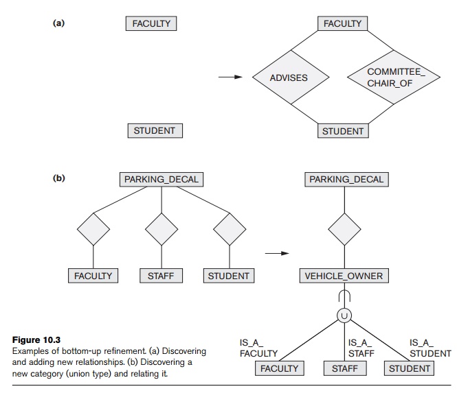
for example, the (min, max) cardinality ratios between COURSE and INSTRUCTOR are obtained during refinement. Figure 10.3(a) shows the bottom-up
refinement primitive of generating relationships among the entity types FACULTY and STUDENT. Two relationships are identified: ADVISES and COMMITTEE_CHAIR_OF. The bottom-up refinement using categorization (union type) is illustrated
in Figure 10.3(b), where the new concept of VEHICLE_OWNER is
discovered from the existing entity types FACULTY, STAFF, and STUDENT; this process of creating a category and the related diagrammatic
notation follows what we introduced in Section 8.4.
Schema (View) Integration. For large databases with many expected users and appli-cations, the view
integration approach of designing individual schemas and then merging them can
be used. Because the individual views can be kept relatively small, design of
the schemas is simplified. However, a methodology for integrating the views
into a global database schema is needed. Schema integration can be divided into
the following subtasks:

Identifying correspondences and conflicts among the schemas. Because the schemas are
designed individually, it is necessary to specify constructs in the schemas
that represent the same real-world concept. These correspondences must be
identified before integration can proceed. During this process, several types
of conflicts among the schemas may be discovered:
Naming conflicts. These are of two types: synonyms
and homonyms. A synonym occurs when
two schemas use different names to describe the same concept; for example, an entity type CUSTOMER in one schema may describe the same concept as an entity type CLIENT in another schema. A homonym occurs
when two schemas use the same name to describe different concepts; for
example, an entity type PART may represent computer parts in
one schema and furniture parts in another schema.
Type conflicts. The same concept may be represented in two schemas by different modeling constructs. For
example, the concept of a
DEPARTMENT may be an entity type in one schema and an attribute in another.
Domain (value set) conflicts. An attribute may have different domains in two schemas. For example, Ssn may be
declared as an integer in one schema and as a character string in the other. A
conflict of the unit of measure could occur if one schema represented Weight in pounds and the other used kilograms.
Conflicts among constraints. Two schemas may impose different constraints; for example, the key of
an entity type may be different in each schema. Another example involves
different structural constraints on a relationship such as TEACHES; one schema may represent it as 1:N (a course has one instructor),
while the other schema represents it as M:N (a course may have more than one
instructor).
Modifying views to conform to one another. Some schemas are modified so
that they conform to other schemas more closely. Some of the conflicts
identified in the first subtask are resolved during this step.
Merging of views. The global schema is created by
merging the individual schemas.
Corresponding concepts are represented only once in the global schema, and
mappings between the views and the global schema are speci-fied. This is the
most difficult step to achieve in real-life databases involving dozens or
hundreds of entities and relationships. It involves a considerable amount of
human intervention and negotiation to resolve conflicts and to settle on the
most reasonable and acceptable solutions for a global schema.
Restructuring. As a final optional step, the
global schema may be analyzed and
restructured to remove any redundancies or unnecessary complexity.
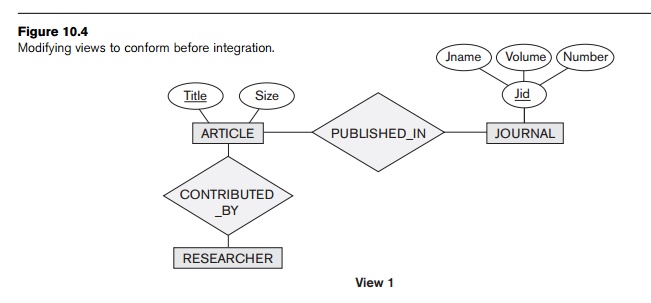
Some of these ideas are illustrated by the rather simple example
presented in Figures 10.4 and 10.5. In Figure 10.4, two views are merged to
create a bibliographic data-base. During identification of correspondences
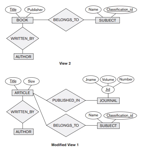
between the two views, we discover that RESEARCHER and AUTHOR are synonyms (as far as this database is concerned), as are CONTRIBUTED_BY and WRITTEN_BY. Further, we decide to modify VIEW 1 to
include a
SUBJECT for ARTICLE, as
shown in Figure 10.4, to conform
to
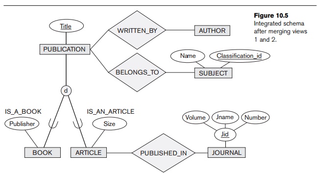
VIEW 2. Figure 10.5 shows the result of
merging
MODIFIED VIEW 1 with VIEW 2. We
generalize the entity types ARTICLE and BOOK into the entity type PUBLICATION, with their common attribute Title. The relationships CONTRIBUTED_BY and WRITTEN_BY are merged, as are the entity types RESEARCHER and AUTHOR. The
attribute Publisher applies
only to the entity type BOOK, whereas the attribute Size and the relationship type PUBLISHED_IN apply
only to ARTICLE.
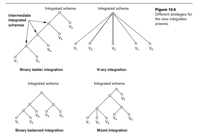
This simple example illustrates the complexity of the merging process
and how the meaning of the various concepts must be accounted for in
simplifying the resultant schema design. For real-life designs, the process of
schema integration requires a more disciplined and systematic approach. Several
strategies have been proposed for the view integration process (see Figure
10.6):
Binary ladder integration. Two
schemas that are quite similar are integrated first. The resulting schema is then integrated with another
schema, and the process is repeated until all schemas are integrated. The
ordering of schemas for integration can be based on some measure of schema
similarity. This strat-egy is suitable for manual integration because of its
step-by-step approach.
N-ary integration. All the views are integrated in
one procedure after an analysis and
specification of their correspondences. This strategy requires computerized
tools for large design problems. Such tools have been built as research
prototypes but are not yet commercially available.
Binary balanced strategy. Pairs of
schemas are integrated first, then the resulting
schemas are paired for further integration; this procedure is repeated until a
final global schema results.
Mixed strategy. Initially, the schemas are partitioned into groups based on their similarity, and each group is
integrated separately. The intermediate schemas are grouped again and
integrated, and so on.
Phase 2b: Transaction
Design. The purpose of Phase 2b, which
proceeds in
parallel with Phase 2a, is to design the characteristics
of known database transactions (applications) in a DBMS-independent way. When
a database system is being designed, the designers are aware of many known
applications (or transactions) that
will run on the database once it is implemented. An important part of database
design is to specify the functional characteristics of these transactions early
on in the design process. This ensures that the database schema will include
all the infor-mation required by these transactions. In addition, knowing the
relative importance of the various transactions and the expected rates of their
invocation plays a crucial part during the physical database design (Phase 5).
Usually, not all of the database transactions are known at design time; after
the database system is implemented, new transactions are continuously
identified and implemented. However, the most important transactions are often
known in advance of system implementation and should be specified at an early
stage. The informal 80–20 rule
typically applies in this context: 80 percent of the workload is represented by
20 percent of the most frequently used transactions, which govern the physical
database design. In applications that are of the ad hoc querying or batch
processing variety, queries and applications that process a substantial amount
of data must be identified.
A common technique for specifying transactions at a conceptual level is
to identify their input/output and functional behavior. By specifying the
input and output parameters (arguments) and the internal functional flow of
control, designers can specify a transaction in a conceptual and
system-independent way. Transactions usually can be grouped into three
categories: (1) retrieval transactions,
which are used to retrieve data for display on a screen or for printing of a
report; (2) update transactions, which are used to enter
new data or to modify existing data in the
database; and (3) mixed transactions,
which are used for more complex applications that do some retrieval and some
update. For example, consider an airline reservations database. A retrieval
transaction could first list all morning flights on a given date between two
cities. An update transaction could be to book a seat on a particular flight. A
mixed transaction may first display some data, such as showing a customer
reservation on some flight, and then update the database, such as canceling
the reservation by deleting it, or by adding a flight segment to an existing
reser-vation. Transactions (applications) may originate in a front-end tool
such as PowerBuilder (Sybase), which collect parameters online and then send a
transaction to the DBMS as a backend.
Several techniques for requirements specification include notation for
specifying processes, which in this
context are more complex operations that can consist of several transactions. Process modeling tools like BPwin as well as
workflow model-ing tools are becoming popular to identify information flows in
organizations. The UML language, which provides for data modeling via class and
object diagrams, has a variety of process modeling diagrams including state
transition diagrams, activity diagrams, sequence diagrams, and collaboration
diagrams. All of these refer to activities, events, and operations within the
information system, the inputs and out-puts of the processes, the sequencing or
synchronization requirements, and other conditions. It is possible to refine
these specifications and extract individual trans-actions from them. Other
proposals for specifying transactions include TAXIS, GALILEO, and GORDAS (see
this chapter’s Selected Bibliography). Some of these have been implemented into
prototype systems and tools. Process modeling still remains an active area of
research.
Transaction design is just as important as schema design, but it is
often considered to be part of software engineering rather than database
design. Many current design methodologies emphasize one over the other. One
should go through Phases 2a and 2b in parallel, using feedback loops for refinement,
until a stable design of schema and transactions is reached.
Related Topics