Chapter: Automation, Production Systems, and Computer Integrated Manufacturing : Process Planning and Concurrent Engineering
Process Planning
PROCESS PLANNING
Process planning involves determining the most
appropriate manufacturing and assembly processes
and the sequence in which they should be accomplished to produce a given part
or product according to specifications set forth in the product design
documentation. The scope and variety of processes that can be planned are
generally limited by the available processing equipment and technological
capabilities of the company or plant. Parts that cannot be made internally must
be purchased from outside vendors. it should be mentioned that the choice of
processes is also limited by the details of the product design. This is a point
we will return to later.
Process
planning is usually accomplished by manufacturing engineers. (Other titles
include industrial engineer, production engineer. and process engineer.) The
process planner must be familiar with the particular manufacturing processes
available in the factory and be able to interpret engineering drawings. Based
on the planner's knowledge, skill, find experience, the processing steps arc
developed in the most logical sequence to make each part. Following is a list
of the many decisions and details usually included within the scope of process
planning.
Interpretation
of design drawings. The part or product design must be analyzed
(materials, dimensions, tolerances, surface finishes, etc.) at the start of the
process planning procedure.
Processes
and sequence. The process planner must select which processes are
required and their sequence. A brief
description of ail processing steps must be prepared.
Equipment
selection. In general, process planners must develop plans
that utilize existing equipment in the plant. Otherwise, the component must be
purchased, or an investment must be made in new equipment.
Tools,
dies, molds, flxtures, and gages. The
process planner must decide what tooling i~ required for each processing step.
The actual design and fabrication of these tools is usually delegated to a
1001design department and tool room, or an outside vendor specializing in that
type of tool is contracted
Methoth
analysis. Workplace layout, smaf tools, hoists for lifting heavy parts, even in some cases hand and body motions
must be specified for manual operations. The industrial engineering department
is usually responsible for this area.
Work
standards. Work measurement techniques are used to set time standards
for each operation.
Cutting
tools and cutting conditions. These
must be specified for machining operations, often with reference to standard
handbook recommendations,
Process
Planning for Parts
For
individual parts, the processing sequence is documented on a form called a route sheet. (Not all companies use the
name route sheet; another name is "operation sheet.") Just as engineering
drawings are used to specify the product design, route sheets are used to spec
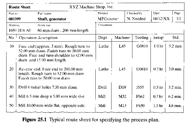
ify the
process plan. They are counterparts. one for product design, the other for
manufacturing. A typical route sheet, illustrated in Figure 25.1, includes the
following information: (1) all
operations to be performed on the work part, listed in the order in which they
should be performed; (2) a brief description of each operation indicating the
processing to be accomplished, with references to dimensions and tolerances on
the part drawing; (3) the specific machine, on which the work is to be done;
and (4) any special tooling, such as
dies, molds, cutting tools. jigs or fixtures, and gages. Some companies also
include setup times, cycle time standards, and other data. It is called a route
sheet because the processing sequence defines the route that the part must
follow in the factory. Some of the guidelines in preparing a route sheet are
listed in Table 25.1.
Decisions
on processes to be used to fabricate a given part are based largely on the
starting material for the part. This starting material is selected hy the pmd(lct
designer Once the material has been specified. the range of possible processing
operations is reduced considerably. The product designer's decisions on
starting material are based primarily on
functional requirements, although economics and manufacturability also play a
role in the selection
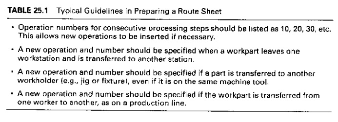
TABLE 25,1 Typical Guidelines in Preparing a Route
Sheet
•Operation
numbers for consecutive processing steps
should be listed as 10, 20, 30, etc, This allows new operations to be inserted
if necessary.
•A new
operation and number should be specified when a work part leaves one
workstation and is transferred to another station
•A new
operation and number should be specified if a part is transferred to another
workholder (e.g., jig or fixture), even if it is on the same machine tool
•A new
operation and number should be specified if the workpart is transferred from
one worker to another, as on a production line.
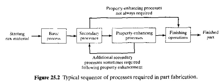
A typical
processing sequence to fabricate an individual part consists of: (I) a basic
process, (2)
secondary processes, (3) operations to enhance physical properties, and (4)
finishing opera/jam. The sequence is
shown in Figure 25.2. A basic process
determines the starting geometry of the workpart. Metal casting. plastic
molding, and rolling of sheet metal arc examples of basic processes. The
starting geometry must often be refined by secondary processes, operations that transform the starting geometry into the
geometry (or close to the final geometry).The secondary processes that might be used
are closely correlated to the basic process that provides the starting
geometry. When sand casting is the basic process, machining operations are
generally the secondary processes. When a rolling mill produces sheet metal,
stamping operations such as punching and bending are the secondary processes. when plastic injection molding is the
basic process, secondary operations are often unnecessary, because most of the
geometric features that would otherwise require machining can be created by the
molding operation. Plastic molding and other operations that require no
subsequent secondary processing are called net
shape processes. Operations that require some but not much secondary
processing (usually machining) are referred to as near net shape processes. Some impression die forgings are in this
category. These parts can often be shaped in the forging operation (basic
process) so that minimal machining (secondary processing) is required.
Once the
geometry has been established, the next step for some parts is to improve their
mechanical and phsyical properties. Operations to enhance properties do not alter the geometry of the part; instead. they
alter physical properties. Heat treating operations on metal parts are the most
common example. Similar heating treatments are performed on glass to produce
tempered glass. For most manufactured parts, these property enhancing
operations arc not required in the processing sequence, as indicated by the
alternative arrow path in Figure 25.2.
Finally ,finishing operations usually
provide a coating on the workpart (or assembly) surface. Examples include
electroplating, thin film deposition techniques, and painting. The purpose of
the coating is to enhance appearance, change color, or protect the surface from
corrosion. abrasion, and .>0 forth.
Finishing operations are not required on many parts: for example, plastic
moldings rarely require finishing. When finishing is required, it is usually
the final step in the processing sequence.
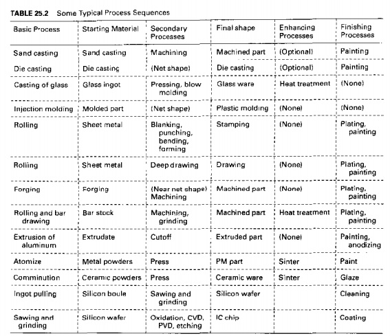
Table
25.2 presents some typical processing sequences for common engineering materials
used in manufacturing.
In most
cases, parts and male rials arriving at the factory have completed their basic
process. Thus, the first operation in the process plan follows the basic
process that has provided the starnng geometry of the part. For example,
machined parts begin as bar stock or
castings
or forgings, which arc purchased from outside vendors. The process plan begins
with the machining operations in the company's own plant. Stampings begin as
sheet metal coils or strips that are bought from the rolling mill. These raw
materials are supplied from outside sources so that the secondary processes,
property enhancing operations, and finishing operations can be performed in the
company's own factory.
In
addition to the route sheet, a more detailed description of each operation is
usually prepared. This is filed in the particular production department office
where the operation is performed. It lists specific details of the operation,
such as cutting conditions and tooling (if the operation is machining) and
other instructions that may be useful to the machine operator. The descriptions
often include sketches of the machine setup.
Process Planning for Assemblies
The type
of assembly method used for a given product depends on factors such as: (1) the
anticipated production quantities; (2) complexity of the assembled product, for
example,
the
number of distinct components: and (3) assembly processes used, for example.
mechanical assembly versus welding. For a product that is to be made III relatively small quantities,
assembly is generally accomplished at individual workstations where one worker
or a team 0: workers perform all of the assembly tasks. For complex products
made in mediurn and high quantities. assembly is usually performed on manual
assembly lines (Chapter 17). For simple products of a dozen or so components.
to be made in large quantities, automated assembly systems arc appropriate. In
any case, there is a precedence order in which the work must be accomplished,
an example of which is shown in Table 17.4.The precedence requirements are
sometimes portrayed graphically on a precedence diagram, as in Figure 17.5.
Process
planning for assembly involves development of assembly instructions similar to
the list of work elements in Table 17.4, hut in more detail. For low production
quantities, the entire assembly is completed at a single station. For high
production on an assembly line, process planning consists of allocating work
elements to the individual stations of the line, a procedure called line balancing (Section 17.4.2). The
assembly line routes the work units to individual stations in the proper order
as determined by the line balancing solution, As in process planning for
individual components, any tools and fixtures required to accomplish an
assemhly task must be determined, designed, and built; and the workstation
arrangement must be laid out.
Make or Buy Decision
An
important question that arises in process planning is whether a given part
should be produced in the company's own factory or purchased from an outside
vendor, and the answer to this question is known as the make or buy decision. If the company does not possess the
technological equipment or expertise in the particular manufacturing processes
required to make the part, then the answer is obvious: The part must be
purchased because there is no internal alternative. However, in many cases, the
part could either be made internally using existing equipment, or it could be
purchased externally from a vendor that possess similar manufacturing
capability.
In our
discussion of the make or buy decision, it should be recognized at the outset
that nearly all manufacturers buy their raw materials from suppliers. A machine
shop purchases its starting bar stock from a metals distributor and its sand
castings from a foundry. A plastic molding plant buys its molding compound from
a chemical company. A stamping press factory purchases sheet metal either from
a distributor or direct from a rolling mill. Very few companies are vertically
integrated in their production operations all the way from raw materials to
finished product. Given that a manufacturing company purchases some of its
starting materials, it seems reasonable to consider purchasing at least some of
the parts that would otherwise be produced in its own plant. It is probably
appropriate to ask the make or buy question for every component that is used by
the company.
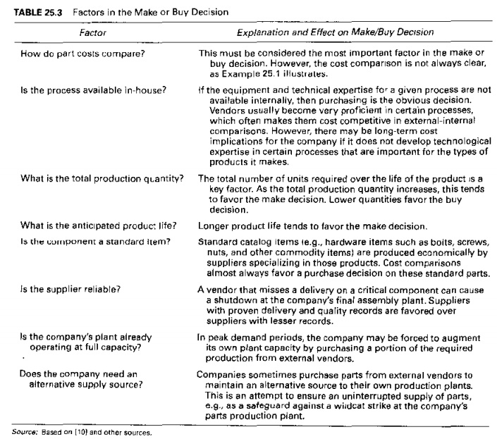
There are
a number of factors that enter into the make or buy decision. We have compiled
a list of the factors and issues that affect the decision in Table 25.3. One
would think that cost is the most important factor in determining whether 10
produce the part or puchase it. ifan outside vendor is more
proficient than the company's own plant in the manufacturing processes used 10 make the part, then the
internal production cost is likely 10 he greater. t~an the purchase price even
after the vendor has included a profit. However. if the decision to purchase results in Idle
equipment and labor in the company's own plant, then the apparent advantage of
purchasing the part may be lost, Consider the following example.
EXAMPLE 25.1 Make or Buy Cost Decision
The quoted price for a certain part is $20 00
per unit for 100 units, The part can be produced in the company's own plant for
$28.00. The cost components of making the part arc as follows:
Unit raw material cost
= $8.00 per unit
Direct labor cos! 6.00 per unit
Labor overhead at 150% = 9.00 per unit
Equipment fixed COS! == 5.00 per unit
Total = 28.00 per unit
Should the
component
by bought or made in-house?
Solution: Although
the vendor's quote seems to favor a buy decision, let us consider the possible impact on plant operations if
the quote is accepted. Equipment fixed cost of $5.00 is an allocated cost based
on an investment that was already made If the equipment designated for this job
becomes unutilized because of a decision to purchase the part, then the fixed
cost continues even if the equipment stands idle. In the same way, the labor
overhead cost of $9.00 consists of factory space, utility, and labor costs that
remain even if the part is purchased. By this reasoning, a buy decision is not
a good decision because it might cost the company as much as $20.00 + $5.00 + $9.00 = $34.00 per unit if it
results in idle lime on the machine that would have been used to produce the
part. On the other hand, if the equipment in question can be used for the
production of other parts for which the in house costs are less than the
corresponding outside quotes. then a buy decision is a good decision
Make or
buy decisions are not often as straightforward as in this example. The other
factors listed in Table 25.3 also affect the decision. A trend in recent years,
especially in the automobile industry, is for companies to stress the
importance of building close relationships with parts suppliers. We will return
to this issue in our later discussion of concurrent engineering (Section 25.3).
Related Topics