Chapter: Civil : Railway Airport Harbour Engineering : Railway Engineering : Suburban Railways in Metro Cities
Mass Rapid Transit System in Delhi
Mass Rapid Transit System in Delhi
At the time of independence, the
population of Delhi was a mere 0.6 million. Starting from this humble figure,
the population of the metropolis grew to 5.7 million in 1981, 12 million in
1998, and 13.78 million in 2001. In the absence of an efficient mass transport
system, the number of motor vehicles in Delhi has increased from 3 million in
1998 to about 5 million in 2006. The large number of vehicles lead to
congestion on roads, which leads to a slowing down of vehicular speeds, thereby
resulting in fuel wastage, increased air pollution, and an increase in road
accidents.
It is a well-known fact that out
of all the cities in the country, the process of urbanization has been the
fastest in Delhi. The city witnesses about 11.7 million transit trips per day,
of which no less than 62% are by public transport. Among the various public
transport options available, 99% are road based and only 1% are rail based,
despite the fact that Delhi has 144 route kilometres of rail tracks converging
into the city from five different directions.
In 1989 a study for an MRTS
network for Delhi was undertaken at the instance of the Delhi Government. The
report brought out the urgent need for a rail-based transit system comprising a
network of 181 route km that consisted of 29.5 km of underground alignments,
40.5 km of elevated route, and 111 km of surface/elevated route length. Nearly
99 km of the route length was analogous with the existing rail network and was
proposed as a surface (or at-grade) corridor. This scheme, which was the basis
of the Delhi Master Plan 2001, however, remained unimplemented.
Corridors for MRTS
There are two distinct types of corridors planned for the MRTS
in Delhi.
Rail corridor The
system is basically located on the surface (at-grade) or on elevated
ground and works on 25-kV ac traction and consists of a rolling stock with
sealed doors and windows that remain closed while in motion.
Metro corridor The
system is underground except for depot connections and lines, which may
be partly at-grade.
1 Phase I of Delhi Metro System
Once the Government decided to
take up the Delhi metro project, the Delhi metro rail corporation (DMRC) was
set up in 1995 for the implementation and subsequent operation of the Delhi
MRTS. The DMRC, however, became effectively functional in 1998, after the
appointment of general consultants and a team to execute the project.
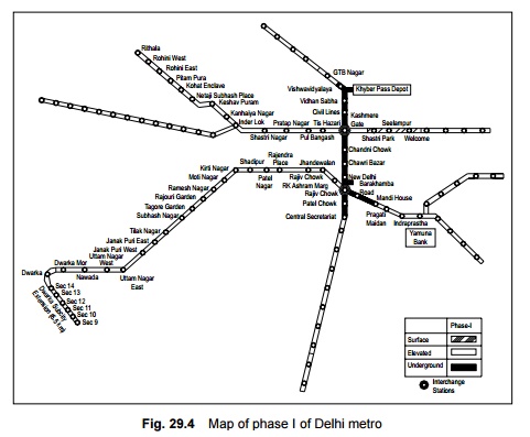
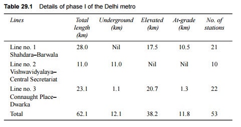
Before starting with the
implementation of the project, the corridors included in phase I were reviewed
and it was finally decided to include three corridors covering a route length
of 62.1 km, which included 12.1 km of underground, 38.2 km of elevated, and
11.8 km of at-grade alignment (Fig. 29.4). The first phase of the Delhi metro
system consists of three lines, as presented in Table 29.1.
The Government decided to take up
the first phase of the metro system in August 1996. The project was started in
right earnest in 1998 and was completed in December 2005.
2 Technical Details of
Delhi Metro
The Delhi metro is planned on the
lines of a world class metro and is equipped with modern communication and
train control systems. In the Delhi metro system, trains are available at a
three-minute frequency during peak periods. The entrances and exits of metro
stations are monitored by flap doors operated by smart cards. For the
convenience of commuters, an adequate number of escalators are installed at the
metro stations. A special feature of the Delhi metro will be its integration
ultimately with other modes of public transport, enabling the commuters to
interchange between one mode and another. The technical details and design
parameters of the Delhi Metro system are briefly described below.
Rolling stock
The rolling stock is the mainstay
of a metro rail system. Metro coaches are lightweight, air-conditioned coaches
with stainless steel bodies that are equipped with features such as three-phase
ac motors. All systems in the coach are monitored by a microprocessor-based
train integrated management system (TIMS). All coaches are of the same type and
each coach is able to accommodate nearly 380 passengers. The coaches have a
width of 3.2 m and an overall length of 22 m (including sitting and standing
passengers).
Some of
the important features of the metro rolling stock are listed below.
(a) Automatic
electric door closing mechanism.
(b) All doors
fully open within 2.5 sec and fully close within 2.5 to 3.5 sec.
(c) The train
cannot move unless all the doors are properly closed and automatically locked.
(d) The train
can be halted with the application of the emergency brake, should a door open
during running.
(e) Emergency
evacuation facility in the form of emergency front door.
(f) Emergency
illumination and ventilation in the case of a power failure.
The initial plan involves running four-coach trains, each
consisting of two motor
coaches that are out fitted with
propulsion equipment and two driving trailer coaches, with a total carrying
capacity of 1500 passengers. Subsequently, six-coach and eight-coach trains are
likely to run to meet increasing traffic demands. These trains are planned to
run at an average speed of 32 to 35 km/hr over an average interstation distance
of 1.1 to 1.3 km.
Signalling and train control
Delhi metro trains are provided with
the latest signalling technology and control system as described in the
subsequent paragraphs.
Signalling It has
been decided that the trains plying underground and in surface corridors
will run at a 3-minute interval in peak hours. The signalling system is
designed for an ultimate headway of two minutes, with a continuous automatic
signalling system comprising of the following special features.
Automatic train protection Automatic
train protection will consist of cab signalling, whereby the
drivers will get information as regards the condition of the line beforehand
and so that they can control the speed of the trains in advance as per the
track status or obstruction. Normally the driver will apply the brakes in the
case of any perceived obstruction on the track. In case a driver fails to do
so, the emergency brakes are applied automatically and all these events are
recorded in the appropriate system device for the purpose of establishing
accountability.
Automatic train supervision Automatic
train supervision (ATS) is a sophisticated computer-based
supervisory system, which will take over the critical functions of the
controller in the control room and will drastically reduce the workload of the
station master. The assistance of ATS is necessary in cases where trains run at
a close headway of 2 minutes. The train describer system of ATS displays the
positions of the trains while they are in motion in visual form in the control
room as well as provide precise information with regard to passengers.
Automatic train operation This
feature is required to be provided for underground corridors
only. It enables the train to be driven without any human intervention, thereby
providing a high level of operational efficiency.
Interlocking of yards An
advanced interlocking system with high-speed (50 km/ hr) turnouts has
been recommended for the yards. The entire section is to be circuited with
audio frequency track circuits, which should eliminate any failures on account
of the insulated joints giving way, thus requiring replacement.
Telecommunication The
telecommunication network between various stations and services is like
a backbone of optic fibre, which will have an enormous capacity for channelling
data and voice communication. It will carry all train control information
through telemetry links, which will bear the details regarding the running of
the train and also the data collected by the passenger information system.
Passengers information system In the
system that has been proposed, the central train describer will provide
precise information to the passengers at every platform on a real time basis by
furnishing online information through the central computer. All the stations
will be provided with centrally synchronized clocks on the various platforms to
maintain time standards. The public address system will enable centralized as
well as local announcements on all stations platforms.
CCTV system Closed
circuit TVs are provided at all the critical locations in the station
premises to monitor every safety aspect.
Power supply
To ensure the continuous
availability of quality power for the running of metro trains, the utmost
efforts have been made to plan and design a power supply system with the degree
of reliability found in other world class metros. The Delhi metro system
derives its operating power in the form of 25-kV ac traction.
Tracks
The design standards for the
track of the metro system are briefly described in the following paragraphs.
Spacing of tracks The metro
routes consist of two broad gauge tracks spaced 4.10 m apart, which is
less than the 4.725 m standard spacing on Indian Railways. The reduced spacing
has been feasible due to the fact that the doors of the coaches are closed and
none of the doors open outward as is the case with the goods wagons of Indian
Railways. The points and crossings are 1 in 12 and 1 in 8.5, as in the case of
Indian Railways.
Gradients The
steepest gradient permissible is 3.0%. Gradients steeper than 2.5% are
adopted only in exceptional cases.
Curves Curves of
radius less than 450 m are adopted sparingly on running lines. No curve
on a running line may have a radius less than 300 m.
Tracks on stations On
stations, tracks are not to be laid on gradient steeper than 0.1% (1 in
1000) and they should also not be laid on curves with radius less than 1000 m.
Vertical curves normally have a radius of 2500 m at points where there is a
change in the gradient. In the case of transition curves, the rules followed
are the same as those on Indian Railways. The other features of the metro track
are as follows.
(a) The metro
track consists of 60-kg UIC rails on level tracks, which rest on concrete
sleepers and are fixed using elastic fastenings (Pandrol clip mark 11). The
sleeper density is 1660 sleepers per km.
(b) The
ballast cushion is prepared using hard stone ballast and measures 300 mm in
thickness.
(c) 60-kg
head hardened rails have been used to enhance the service life of the rails,
particularly on sharp curves and steep gradients.
(d) To
minimize the need for track maintenance and reduce the dimensions of structures
that are consequential to the quality of the run, a 'ballastless track' is
being laid on elevated sections, viaducts, and tunnels. These stretches are
provided with 60-kg rails that are fixed with the help of Vossloh fastenings.
(e) To
improve the standard of maintenance and ensure a comfortable ride, rails are
mostly welded as long welded rails and efforts have been made to ascertain that
the entire track is almost 'joint-less'. For this purpose, even the turnouts
have been integrated into the long welded rails. Specially designed turnouts
are used with thick web switches and CMS crossings by means of welded leg
extensions.
Metro stations
There are about 53 metro
stations, including 12 underground stations on phase 1 of the Delhi metro.
Metro stations are normally two-line stations with side or island platforms.
The platforms are 185 m long, so as to accommodate eight-coach trains. The
platform surface lies 1.08 m above the rail level, so that the floor of the
coaches is almost level with the platform. The width of the platform is
normally 6 m in the case of side platforms and 10 m in the case of island
platforms.
Tracks at stations with side
platforms are placed 4.1 m apart, while these with island platforms, are placed
around 13.3 m apart. Stations located in well-populated areas are normally
spaced 1 km apart. The interstation distance can, however, vary marginally to
suit site conditions.
Stations situated on an elevated
corridor along the central verge of the road can be provided with tracks at a
height of about 12 m above the road level. Most of the underground metro
stations are generally two-level stations between 270 m to 300 m in length. A
typical station is 20 m wide and 15 m deep. The first level boasts of various
passenger facilities together with ventilation and electronics and
communication equipment rooms and the lower level comprises the platform with
electric equipment rooms at each end of the box. Island platforms are provided
with stations that are adjacent to board tunnel sections while side platforms
are provided with cut and cover tunnels. All stations have been designed with
the option to accommodate platform screen doors.
3 Civil Works
Some of the new technologies and
innovations in construction techniques that are being deployed for the Delhi
MRTS are briefly mentioned here.
Construction of bridges
Several innovative construction
techniques were used in the construction of the bridges. For example, a new
Yamuna bridge (12 spans of 46.2 m each) was constructed using modern techniques
during the construction of the Delhi Metro. The substructure of this bridge
consists of capsule-shaped piers that rest on well (caisson) foundations of 10
m diameter with a steining thickness of 1.0 m, which have been sunk up to a
depth of about 39 m. The 'jack-down' method, supplemented with air/water
jetting, has been used for sinking the wells. This method involved pushing the
well assembly down into the ground by applying pressure to counter the
resistance arising due to skin friction around the periphery of the wells and
below the cutting edge. Soil dredging has been carried out inside the well
simultaneously. The new techniques resulted in the faster sinking of the wells.
Also, the wells have been sunk plumb into the water with the help of minimum
tilts or shifts.
The superstructure of the bridge
comprises of a single box girder of a constant depth of 3.5 m that has been
launched using an incremental launching technique. This technique involved
casting the girder on the bridge approach behind the abutment in segments of
length 23.1 m, which is half the length of one span. Each segment has been cast
behind the previous unit. After a sufficient concrete strength was attained,
the new unit was post-tensioned to the previous one. The assembly of units was
pushed forward to permit the casting of the succeeding segment. This technique
resulted in a single continuous girder of a length of 554 m with no joints.
The
innovative features of the Yamuna bridge are summarized below.
(a) Second
incrementally launched bridge in India, the first being the Panvel Nadi bridges
of the Konkan Railway.
(b) First box
girder in India carrying dual unballasted tracks.
(c) An
innovative technique for sinking the wells; the jack-down method has been
adopted for sinking 15 wells. Ground anchors have been installed near the well
staining, which have been used for taking the reaction of the specially
designed hydraulic jacks at the top.
Elevated viaduct
The elevated viaduct simply
comprises of supported spans with lengths varying from 21.1 m to 29.1 m. It has
been constructed by the precast segmental technique with epoxy bonded joints
and traditional internal pre-stressing. The span lengths have been determined
mainly on the basis of the site constraints at the ground level for the
location of the foundations and piers. All precasting has been done at a
centralized casting yard.
An aesthetic form of the
substructure has been evolved so as to harmonize with the flow of the forces.
In this structure the pier gradually tapers outward at the top to support the
bearings under the box webs. All the piers have been cast in place using rigid
steel which was poured in a single attempt in order to avoid any construction
joints. The use of bolts in the concrete has not been permitted. Bored piles of
a diameter of 1.2 m that have been cast in situ have been included by employing
modern hydraulic rigs. To ensure a standard span, groups of nine piles with a
length of 23 m to 28 m have been stacked in the soil. In rocky terrains, piles
have been stacked in the rock in groups of six up to a depth equal to 1.5 to
3.0 times the diameter of the pile, depending on the type of rock encountered.
A temporary casing has been employed for the stabilization of the bore holes.
Cut and cover tunnels
It is possible to construct
tunnels by excavating the ground surface, hence the cut and cover method has
been employed for tunnel construction in these stretches. Cut and cover tunnels
are generally designed as a single structural unit with a dividing wall, and
walkways for each track giving an average box width of 10 m. The over-run
tunnels are used as sidings and contain three tracks while at the depot spur
the tunnels contain four tracks. The construction methodology for cut and cover
tunnels is similar to that of cut and cover stations.
Cut and cover construction,
though economical, results in a lot of public inconvenience if planned
improperly. As such, it requires exhaustive planning with regard to utilities,
traffic management, and environmental concerns such as cutting of trees and air
and noise pollution.
Bored tunnel construction
The bored tunnel construction
technique has been used at many places in the metro corridor tunnels. The
internal diameter of such tunnels is about 5.6 m and they are generally lined
with precast reinforced concrete segments. Tunnel boring machines (TBMs) have
been used in place of conventional tunnelling methods that employing various
hand mining techniques, since conventional tunnelling methods suffer from major
handicaps with regard to slower progress and risks to existing structures in
the vicinity of tunnel excavation.
Since the bored tunnel
construction for the Delhi metro involved tunnelling through both quartzite and
soft ground, two types of TBMs have been used, namely, rock TBM for rocky
ground and earth pressure balance machine (EPBM) for soft ground. In the case
of an EPBM, the excavated face is supported by pressurizing the soil that has
been dug up, together with additives if necessary, to give it a plastic
texture. A screw auger is used to remove the excavated material. The earth
pressure within the cutter head is maintained by balancing the rate at which it
advances with the rate at which the spoil material is removed and adjusting the
parameters as required. The gap between the excavation surface and the precast
concrete lining is filled by means of an automatic injection from the tail of
the machine, which minimizes ground settlement. Watertightness at the tail is
ensured by injecting grease into the three rows of brush seals.
4 Underground Versus Elevated Alignment
Underground construction is a
much costlier option than elevated alignment. The current average cost per
route kilometre for construction on an elevated alignment, including stations,
rolling stock, signalling, and electrical equipment as well as land and incidental
works, is Rs 1000 million as compared to Rs 3000 million for underground
construction. On account of the vast cost difference, the choice of underground
construction is restricted to areas where elevated alignment is not suitable.
In the case of Delhi metro, underground construction is restricted to the core
area of Delhi on the North-South and East-West corridors, which intersect in
the Connaught Place area. Most of the route length outside the core area is
likely to be constructed as an elevated route.
In the case of elevated segments
of the MRTS, the alignment on city roads usually follows the central verge of
the road. Piers of about 2 m diameter are spaced 20-30 m apart along the
central verge. The arrangement of girders above the pier cap is shown in the
general arrangement given in Fig. 29.5. Tracks are generally laid 8.5-9.5 m
above the road level on elevated routes outside the station. The desirable
minimum width of the roads for locating an elevated MRTS on the same is 30 m,
although a road width of 40-45 m is preferable. The geometry of the road should
be favourable for the adoption of curves adhering to the minimum MRTS
standards. In the case of underground construction on stretches outside the
station, the rail level lies at a minimum depth of 9 m below the road surface.
This is done with the object of 2-3 m of space below the road for electrical
cables, telephone cables, and drains.
A corridor need not be wholly
underground or elevated. An underground corridor in the core city area could
get converted into an elevated corridor in the outer parts, where the
conditions are favourable for such constructions. It is crucial that an extra
stretch of aligned road surface be available between the point where the
underground section ends and the elevated section starts. The alignment in this
stretch should rise from about 9 m below the ground to 9 m above the road
level. In order to ensure that the length of the at-grade stretch is not unduly
long, the tracks are provided with a steep gradient for negotiating this
difference in the level. This stretch can measure 400-500 m in length depending
on the site characteristics.
In the at-grade stretch, the MRTS
tracks are walled on both sides, their outer faces being nearly 10 m apart.
This implies that the road width is effectively reduced by about 11 m on this
stretch. This factor is of great importance in choosing the location for an
at-grade ramp.

Schedule of dimensions
The Delhi Metro Rail Corporation
has drawn up a schedule of the dimensions for its system. These dimensions
should normally be adhered to when undertaking new works and finding
alternatives to existing works on BG lines (1676 mm), except in exceptional
cases where the sanction of the commissioner of railway safety has to be
specifically obtained.
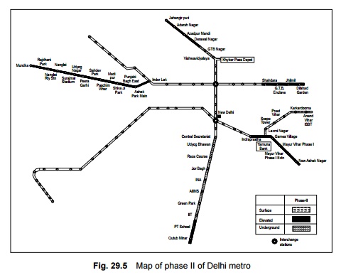
5 Delhi Metro Phase II
The Delhi Metro Rail Corporation
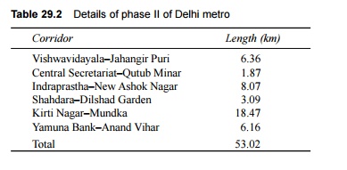
has already made plans for phase II of Delhi metro (Fig. 29.5). The total route
length is about 54 km as per the details given in Table 29.2.
Table 29.2 Details of phase II of
Delhi metro
The preparation of detailed
project reports for the corridors of phase II of the Delhi metro is complete
and the Government of Delhi has already made budgetary provisions for the same.
Work on phase II is scheduled to be completed before 2010.
With the success of the Delhi
metro, several state governments have approached the DMRC for preparing
detailed project reports for metros for their cities. Such reports have already
been prepared for Bangalore and Hyderabad and submitted to the Karnataka and
Andhra Pradesh state governments, respectively. Investigations/ studies are
presently underway for the preparation of detailed project reports for
constructing metro rail systems in Mumbai, Ahmedabad, Kolkata, and Kochi.
Related Topics