Chapter: Civil : Foundation Engineering : Footings And Rafts
Footings And Rafts

FOOTINGS AND RAFTS
P1=800kN
P2
=1000kN
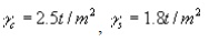
qo =20
t/m2,M15, fy=415kN/m2
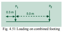
Fig. 4.51 Loading
on combined footing
Column size:
400x400mm.
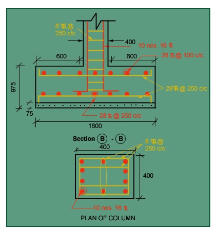
See Fig 4.54 for
details of footing. Column design
Let pt=0.8%
Ax
=.008A; Ax=0.992A
Clause.39.3 of IS 456-2000
A=146763.8mm2
Ax
=1174.11 mm2, =145589.746mm2
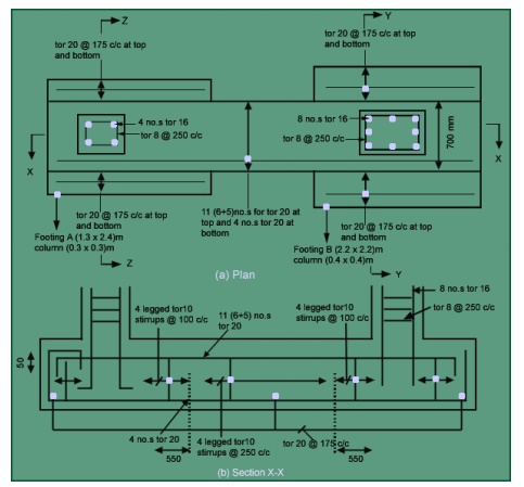
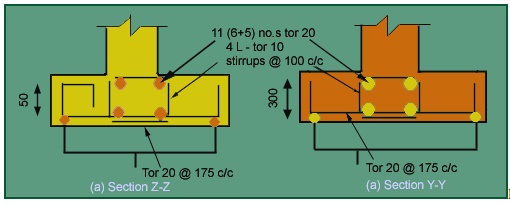
Provide footing of
400x400size for both columns.
Using 8-16 j as main
reinforcement and 8 j @250c/c as lateral tie
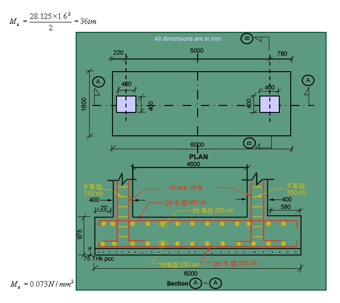
Design of Footing
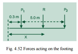
Fig. 4.52 Forces
acting on the footing
Resultant of Column
Load
R =1800 kN acting
3.08m from the boundary.
Area of the footing
:
Taking length L=6m,
Depth of footing Df=0.9m,
Width of
footing, 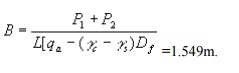 =1.549m.
Therefore, provide
footing of dimension 6m x 1.6m
Soil Pressure q = 180/
6 x 1.6 =18.75 t/m2< 20 t/m2 OK.
qu=28.125
t/m2
Soil pressure
intensity acting along the length =B x
=1.6x28.125 =45t/m.
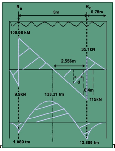
RB
=119.88kN, RC =150.12kN.
Thickness of Footing
i. Wide beam shear:
Maximum shear force
is on footing C,SF=115.02KN
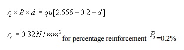
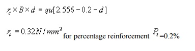
for percentage reinforcement Pt
=0.2%
0.32 x d x 1.6=45
[2.556-0.2-d]
d=1.1m
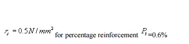
for percentage reinforcement =0.6% 0.6 x d x 1.6=45 [2.556-0.2-d]
d=0.847m.D=900mm.OK.
ii.Two way Shear Thickness of Footing
i. Wide beam shear:
Maximum shear force
is on footing C,SF=115.02KN
for percentage
reinforcement Pt=0.2%
0.32 x d x 1.6=45
[2.556-0.2-d]
d=1.1m
for percentage reinforcement Pt
=0.6%
0.6 x d x 1.6=45
[2.556-0.2-d]
d=0.847m.D=900mm.OK.
ii.Two way Shear
Column B
d=0.415m.
Column A
2d[(0.4+d)+(0.42+d/2)]
x 96.8=120-28.125[(0.4+d)(0.42+d/2)] d=0.3906m
dreqd
=0.85mm
Dprovided
=900mm, dreqd =850mm.OK.
Flexural reinforcement
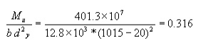
Along Length
Direction
Pt =0.354%
Ptprovided=0.6%
Astrequired=5100
mm2/mm
Provide 28 j @120mmc/c at top
and bottom of the footing
Along width
direction
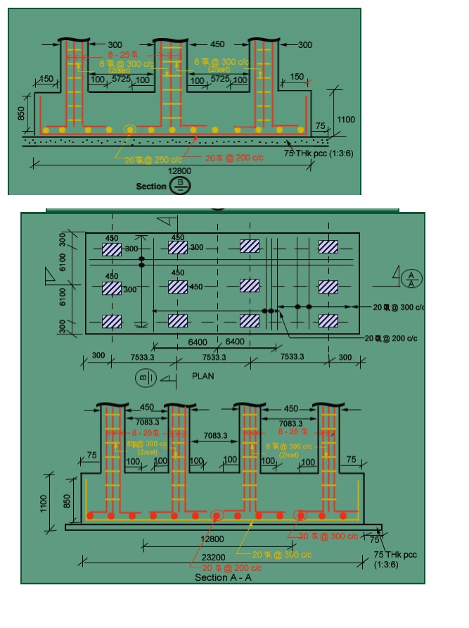
Raft Footing Design the raft footing for the
given loads on the columns and spacing between the columns as shown below.
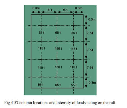
Fig 4.57 column
locations and intensity of loads acting on the raft
a) Column sizes
Take size of the columns are as: 300*450 mm
for load of less than 115 ton
450*450 mm for a
load of greater than 115 ton
Thickness of raft
Two way shear
The shear should be
checked for every column, but in this case because of symmetry property
checking for 115 t, 150 t, and 55 t is enough.
For 150 t column
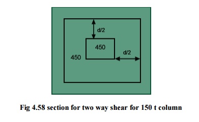
Fig 4.58 section
for two way shear for 150 t column
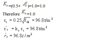
IS: 456-1978,
bc=450/450=1.0
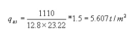
4(0.45+d)*d*96.8=150*1.5-5.607(0.45+d)2
Therefore d=0.562 m
For 115 t column

Fig 4.59 section
for two way shear for 115 t column
2(0.45+d+0.15+0.3+d/2)
d*96.8=115*1.5-5.607(0.45+d)(0.3+0.15+0.5d)
Therefore d=0.519 m
For 55 t column
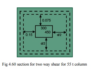
Fig 4.60 section
for two way shear for 55 t column
2(0.45+0.075+0.5d+0.15+0.3+0.5d)
d*96.8=55*1.5-5.607(0.45+0.5d+0.075)(0.3+0.5d+0.15)
Therefore d=0.32 m
The guiding
thickness is 0.562m and code says that the minimum thickness should not be less
than 1.0m.
let provide a
overall depth of 1.1m=D
dpdv
=1100-75-20/2=1015mm.
To calculate k
& l Stiffness factors
There are two
criterions for checking the rigidity of the footing:
Plate size used is
300*300 mm.
For clays: Mus=0.5,
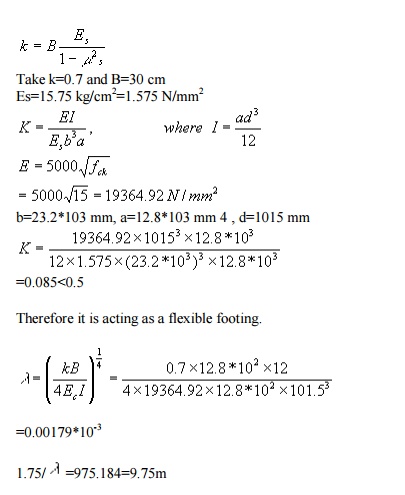
If column spacing
is less than 1.75/ l, then the footing is said to
be rigid.
Therefore the given
footing is rigid.
One criterion
showing the footing is flexible and another showing that the given footing is
rigid. Both are contradicting each other, so design the footing for both
criterions.
Reinforcement in width direction
From SP-16 graphs
Pt
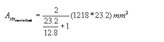
=0.102%, but minimum is 0.12%.
Adx =(0.12*1000*1015)/100=1218
mm2
Provide 20 mm
diameter bars @250 c/c along shorter direction in bottom.
Reinforcement in length direction
Provide 20 mm
diameter bars @250 c/c in longer direction.
Clause 33.3.1
Provide 20 mm
diameter bars @ 200 c/c in central band and 20 mm diameter bars @300 c/c at
other parts along shorter direction at bottom.
Shear (wide beam shear criterion)
In width direction
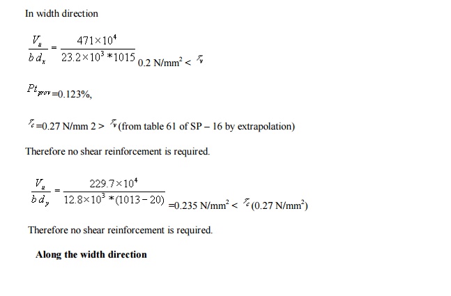
=0.235 N/mm2
< r(0.27 N/mm2)
Therefore no shear
reinforcement is required.
Along the width
direction
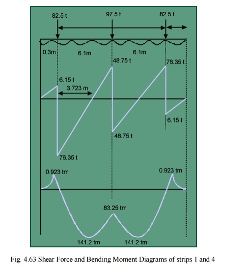
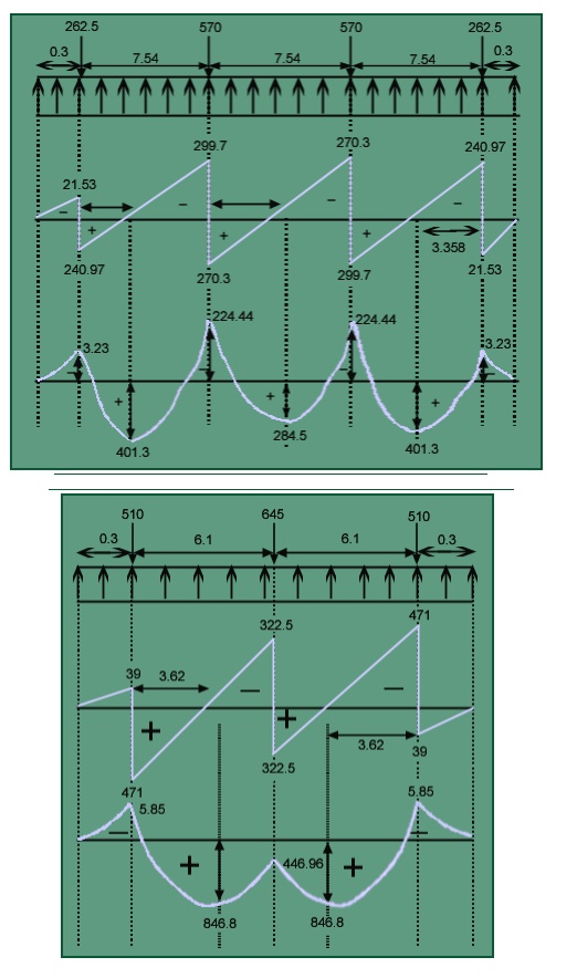
Fig. 4.63 Shear
Force and Bending Moment Diagrams of strips 1 and 4
In width direction:
Strip1/4:- =141.2tm
Strip2/3
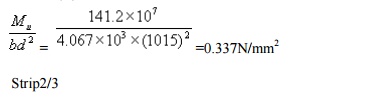
Fig. 4.64 Shear
Force and Bending Moment Diagrams of strips 2 and 3
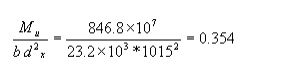
Strip 2/3
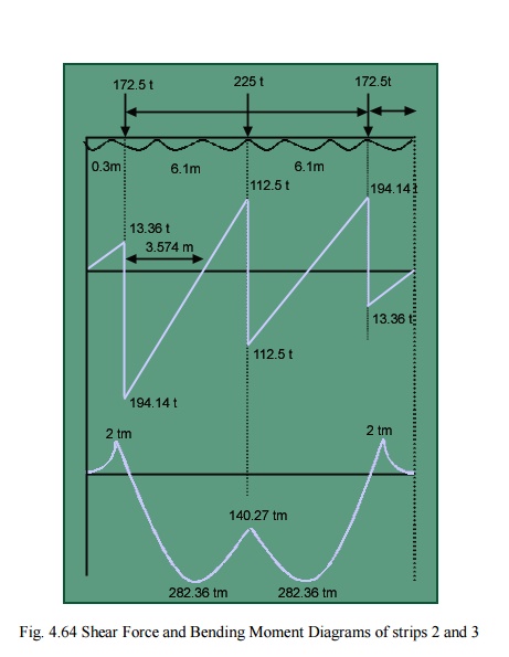
Mu
=282.36tm
M/bd2 = 0.364N/mm2
Minimum Pt=0.12%has to be provided.
Provide 20 j @200c/c in centre
band and 20 j @300c/c at other parts along the shorter direction.
1. Shear check
Along width
direction:-
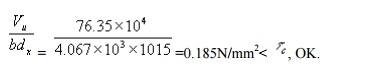
For strip1/4:
Va=76.35t
For strip 2/3:
Va=159.14
t
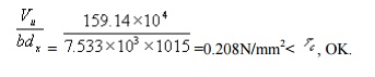
Hence no shear
reinforcement is required.
Development Length
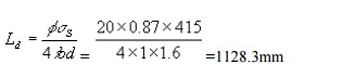
At the ends, length
of bar provided=150mm.
Extra length to be
provided=1128.3-150-8x20=818.3mm.
Provide a
Development length of 850mm
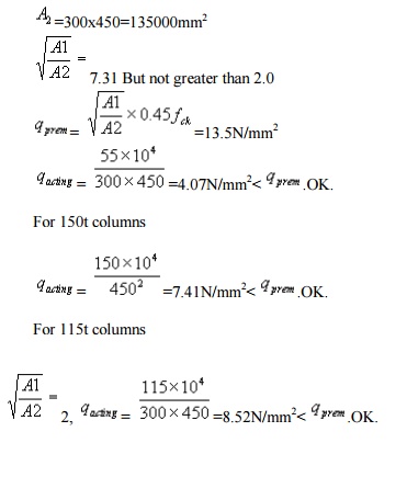
3. Transfer of load at the base of the
column:-
For end column;
A1=2650X2725=7.22125x106mm2
A2=300x450=135000mm2
Related Topics