Chapter: Civil : Foundation Engineering : Piles
Piles
PILES
DESIGN METHODOLOGY FOR PILES
The detailed design methodology of piles is
described in the following sections.
REQUIREMENT FOR DEEP FOUNDATIONS
Generally for
structures with load >10 t/m2 ,
we go for deep
foundations. Deep foundations are used in the
following cases:
Huge
vertical load with respect to soil capacity.
Very
weak soil or problematic soil.
Huge
lateral loads eg. Tower, chimneys.
Scour
depth criteria.
For
fills having very large depth.
Uplift
situations (expansive zones)
Urban
areas for future large and huge construction near the existing building.
CLASSIFICATION OF PILES
1.
Based on material
Timber
piles
Steel
piles
Concrete
piles
Composite piles (steel + concrete)
2. Based on method of installation
Driven
piles ----(i) precast (ii) cast-in-situ.
Bored piles.
3. Based on the degree of disturbance
Large
displacement piles (occurs for driven piles)
Small
displacement piles (occurs for bored piles)
POINTS TO BE CONSIDERED FOR CHOOSING
PILES
� Loose
cohesion less soil develops much greater shaft bearing capacities if driven
large displacement piles are used.
� Displacement
effect enhanced by tapered shafts.
� Potential
increased of shaft capacities is undesirable if negative friction is to be
feared. (Negative friction is also called drag down force)
� High
displacement piles are undesirable in stiff cohesive soils, otherwise excessive
heaving takes place.
� Encountered
with high artesian pressures on cased piles should be excluded. (Mainly for
bridges and underwater construction)
� Driven
piles are undesirable due to noise, damage caused by vibration, ground heaving.
� Heavy
structures with large reactions require high capacity piles and small diameter
cast-in-situ piles are inadequate.
� PILE
CLASSIFICATION
� Friction
piles.
� End
bearing piles.
� Compaction
piles.( Used for ground movement, not for load bearing )
�
Tension piles/Anchored piles.(To resist
upliftment)
�
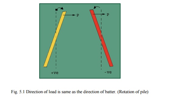
Butter piles (Inclined) --- +ve and -ve.

Fig.
5.1 Direction of load is same as the direction of batter. (Rotation of pile)
Raymond piles. (Driven cast-in-situ piles, first
tapered shell is driven and then cast)
Franki Piles (Driven
cast-in-situ piles, first casing is driven upto 2m depth, then cast a block
within that casing and then drive the block. When it reaches the particular
depth, take out the casing and cast the piles.)
Underreamed piles
(bored cast-in-situ piles, bulbs used, hence not possible to install in loose
sand and very soft clays.)
PILES IN CLAY
Zone of influence
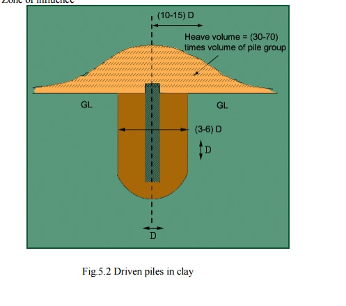
Fig.5.2
Driven piles in clay
The heaving effect can
be felt upto (10 -15) D from the centerline of the pile. Due to driving load,
pressure is generated and as a result heaving occurs. Afterwards with time, the
heaved part gets consolidated and strength gradually increases as the material
regains shear strength within 3 -6 months time after the installation of the
pile. This regain of strength is called thixotrophy.
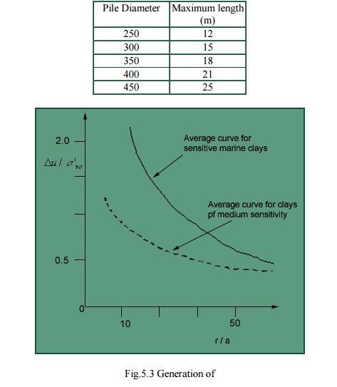
On the first day some
part of the pile will be driven and on the second day some part of the pile may
move up due to the gain of shear strength. This is known as the wakening of
the pile. By the driving force, the extra pore pressure generated is (5 -7)
times the Cu of the soil.
Bearing capacity of the pile is 9 Cu.
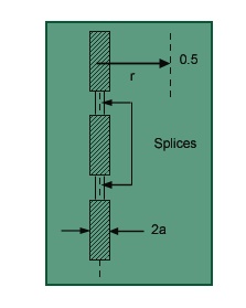
Hence due to this property, maximum single length of the pile theoretically can
be upto 25m but 10-12m is cast at a time. Then by splicing technique the
required hired length of the pile is obtained. Special types of collars are
used so that the splices become weak points. Concrete below the grade M20 is
never used.
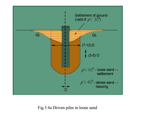
PILES IN SAND
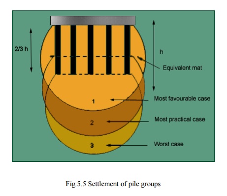
SETTLEMENT
OF PILE GROUPS
Assume 2V:1H dispersion
for settlement of pile groups.
CODAL PROVISION
SAFE LOAD ON PILES/PILE GROUPS ( Ref. IS: 2911 Part IV 1979 ) Single
pile: 1. Safe load = Least of the following loads obtained from routine
tests on piles :
![]()
2/3
of the final load at which total settlement is 12mm.
![]()
50% of the final load at which settlement is 10% of
the pile dia.( for uniform dia. piles) and 7.5% of bulb dia. (for Underreamed
piles)
![]() 2/3 of the final load
at which net settlement is 6mm.
2/3 of the final load
at which net settlement is 6mm.
![]()
Consider pile as column and find the total
compressive load depending on the grade of concrete and dimensions. Eg.
Consider a 300mm dia pile made of M20 concrete.. acc = 5N/mm2
Therefore, ultimate load =
.
Fig
5.40 Multiple Under Reamed Pile
Under reamed piles are
bored cast-in-situ concrete piles having one or more number of bulbs
formed by enlarging the pile stem. These piles are best suited in soils
where considerable ground movements occur due to seasonal variations,
filled up grounds or in soft soil strata. Provision of under reamed bulbs has
the advantage of increasing the bearing and uplift capacities. It also provides
better anchorage at greater depths. These piles are efficiently used in machine
foundations, over bridges, electrical transmission tower foundation sand water
tanks. Indian Standard IS 2911 (Part III) - 1980 covers the design and
construction of under reamed piles having one or more bulbs. According to the
code the diameter of under reamed bulbs may vary from 2 to 3 times the stem
diameter depending upon the feasibility of construction and design
requirements. The code suggests a spacing of 1.25 to 1.5 times the bulb
diameter for the bulbs. An angle of 45 0 with horizontal is recommended for all
under reamed bulbs. This code also gives Mathematical expressions for
calculating the bearing and uplift capacities.
From the review of the
studies pertaining to under reamed piles, it can be seen that ultimate bearing
capacity of piles increases considerably on provision of under- reamed bulbs
(Neumann and P&g, 1955, Subash Chandra and Kheppar, 1964, Patnakar, 1970
etc.). Pile load capacity was found to vary with the number of bulbs and with
the spacing ratio S / S/Du or
S/d adopted (where S = distance between the piles, Du= diameter of under reamed bulbs and d = diameter of piles).
Table summarizes the various recommendations made for the selection of S / S/Du and S/d for the optimum pile
load capacity. It can be seen that some of these recommendations differ from
those given in IS 2911 (Part III), 1980.
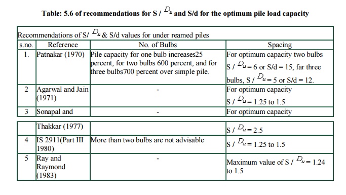
Table:
5.6 of recommendations for S / D u and
S/d for the optimum pile load capacity
The choice of an
under-reamed pile in unstable or water-bearing ground is generally to be
avoided. There is a danger of collapse of the under-ream, either when personnel
are down the hole, or during concreting.
Important Notes: On
the basis of limited experimental studies conducted on model under reamed piles
in cohesion less soil the following conclusions are drawn.
1. By providing under reamed bulbs the ultimate load capacities of piles increases significantly.
2. The ultimate load bearing capacities of the under reamed piles with angle of under reamed bulbs of 45 0 and zero are almost same.
3. Three or more under reamed bulbs are advantageous only when the spacing ratio (S / Du) is two or less, and when (S / Du) is greater than two, multi-under reamed piles do not have specific advantages.
4. The ultimate load bearing capacities of piles are maximum when the spacing between two under reamed bulb is 2.5 times the diameter of the under reamed bulb. It appears that the spacing between two under reamed bulbs suggested in (1.25 to 1.5 times) IS 2911(1980) is not the optimum,
5. The expression suggested in IS 2911(1980) can be used for predicting the ultimate load carrying capacity of under reamed piles with spacing ratio (S / Du) less than.
Related Topics