Chapter: Measurements and Instrumentation : Electrical and Electronics Instruments
Electrodynamometer Wattmeters: Construction, Theory, Errors
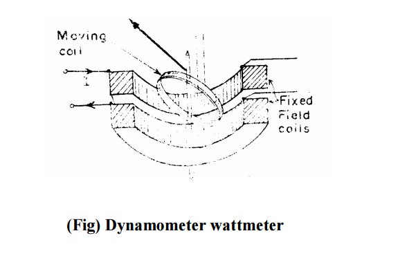
Electrodynamometer Wattmeters
These instruments are similar in design and construction to electrodynamometer type ammeters and voltmeters.
The two coils are connected in different circuits for measurement of power.
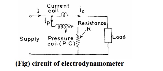
The fixed coils or “ field coils” arc connected in series with the load and so carry the current in the circuit.
The fixed coils, therefore, form the current coil or simply C.C. of the wattmeter.
The moving coil is connected across the voltage and, therefore, carries a current proportional to the voltage.
A high non-inductive resistance is connected in series with the moving coil to limit the current to a small value.
Since the moving coil carries a current proportional to the voltage, it is called the ‘ ‘ pressure coil’ ’ or “ voltage coil” or simply called P.C. of the wattmeter.
Construction of Electrodynamometer Wattmeter
Fixed Coils
The fixed coils carry the current of the circuit. They are divided into two halves.
The reason for using fixed coils as current coils is that they can be made more massive and can be easily constructed to carry considerable current since they present no problem of leading the current in or out.
The fixed coils are wound with heavy wire. This wire is stranded or laminated especially when carrying heavy currents in order to avoid eddy current losses in conductors. The fixed coils of earlier wattmeters were designed to carry a current of 100 A but modem designs usually limit the maximum current ranges of wattmeters to about 20 A. For power measurements involving large load currents, it is usually better to use a 5 A wattmeter in conjunction with a current transformer of suitable range.
Damping
Air friction damping is used.
The moving system carries a light aluminium vane which moves in a sector shaped box. Electromagnetic or eddy current damping is not used as introduction of a permanent magnet (for damping purposes) will greatly distort the weak operating magnetic field.
Scales and Pointers
They are equipped with mirror type scales and knife edge pointers to remove reading errors due to parallax.
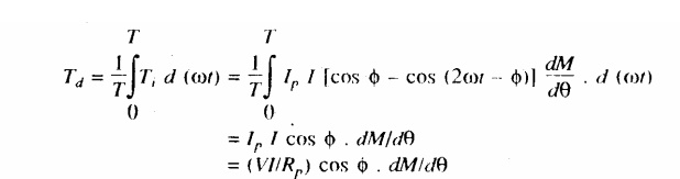
Theory of Electrodynamometer Watt-meters
It is clear from above that there is a component of power which varies as twice the frequency of current and voltage (mark the term containing 2 Ȧt).
Average deflecting torque
Controlling torque exerted by springs Tc= Kș
Where, K = spring constant; ș= final steady deflection.
Errors in electrodynamometer
i) Errors due to inductance effects
ii) Stray magnetic field errors
iii) Eddy current errors
iv) Temperature error
Related Topics