Chapter: 9th Science : Electric charge and electric current
Electric current
Electric
current
When the charged object
is provided with a conducting path, electrons start to flow through the path
from higher potential to lower potential region. Normally, the potential difference
is produced by a cell or battery. When the electrons move, we say that an
electric current is produced. at is, an electric current is formed by moving
electrons.
1. Direction of current
Before the discovery of
the electrons, scientists believed that an electric current consisted of moving
positive charges. Although we know this is wrong, the idea is still widely
held, as the discovery of the flow of electrons did not a ect the basic
understanding of the electric current. The movement of the positive charge is
called as ‘conventional current’. The flow of electrons is termed as ‘electron
current’. is is depicted in Figure 2.6.
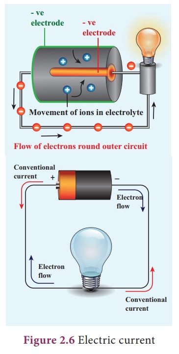
In a battery, the
potential of the positive terminal is maintained positive and the negative
terminal is negative. Electrons are removed from the positive terminal and
enriched at the negative terminal internally by means of chemical reaction or
other processes. When a connection is given externally by a conducting wire, electrons
flow from the negative terminal to the positive of the cell. Conventional
current or simply the current, behaves as if positive charges cause the current
ow. Although in reality it is the electron that moves in one direction, in
equivalence, we consider as if it is the positive charges are moving in the
opposite direction. is is taken as the direction of ‘current’.
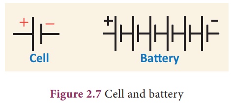
In electrical circuits
the positive terminal is represented by a long line and negative terminal as a
short line. Battery is the combination of more than one cell as shown in the
Fig. 2.7.
2. Measurement of electric current
We can measure the value
of current and express it numerically. Current is the rate at which charges flow
past a point on a circuit.
That is, if q is the
quantity of charge passing through a cross section of a wire in a time t,
quantity of current (I) is represented as,
I = q/t
The standard SI unit for
current is ampere with the symbol A. Current of 1 ampere means that there is
one coulomb (1C) of charge passing through a cross section of a wire every one
second (1 s).
1 ampere = 1 coulomb / 1
second (or)
1 A = 1 C / 1 s = 1CS-1
Ammeter is an
instrument used to measure the strength of the electric current in an electric
circuit.
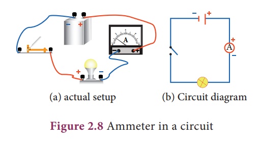
The ammeter is connected
in series in a circuit where the current is to be found. . The current flows
through the positive ‘+’ red terminal of ammeter and leaves from the negative
‘–’ black terminal.
Exercise 2.2
Suppose, 25 C of charge
is determined to pass through a wire of any cross section in 50 s, what is the
measure of current?
Solution:
I = q / t = (25 C) / (50
s) = 0.5 C/s = 0.5 A
Exercise 2.3
The current flowing
through a lamp is 0.2A. If the lamp is switched on for one hour, What is the
total electric charge that passes through the lamp?
Solution:
I = q / t; q = I x t
Time has to be in
second.
∴1hr
= 1x 60 x 60 s= 3600 s
q = I x t = 0.2A x 3600s
= 720C
3. Electromotive force (e.m.f)
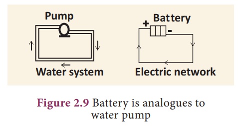
Imagine that two ends of
a water pipe lled with water are connected. Although lled with water, the water
will not move or circle around the tube on its own. Suppose, you insert a pump
in between and the pump pushes the water, then the water will start moving in
the tube. Now the moving water can be used to produce some work. We can insert
a water wheel in between the flow and make it to rotate and further use that rotation
to operate machinery.
Likewise if you take a
circular copper wire, it is full of free electrons. However, they are not
moving in a particular direction. You need some force to push the electrons to
move in a direction. The water pump and a battery are compared in Figure 2.9.
Devices like electric
cells and other electrical energy sources act like pump, ‘pushing’ the charges
to flow through a wire or conductor. The ‘pumping’ action of the electrical
energy source is made possible by the ‘electromotive force (e.m.f). The
electromotive force is represented as (e). The e.m.f of an electrical energy
source is the work done (W) by the source in driving a unit charge (q) around
the complete circuit.
ε = W/q
where, W is the work
done or the non-electrical energy converted into electrical energy measured in
joules and q is the amount of charge. The SI unit of e.m.f is joules per
coulomb (JC-1) or volt (V). In other words the e.m.f of an electrical
energy source is one volt if one joule of work is done by the source to drive
one coulomb of charge completely around the circuit.
Exercise 2.4
The e.m.f of a cell is
1.5V. What is the energy provided by the cell to drive 0.5 C of charge around
the circuit?
Solution: ε = 1.5V and q
= 0.5C
ε = W/q; W= ε x q; Therefore W = 1.5 x 0.5 =
0.75J
4. Potential difference (p.d)
One does not just let
the circuit connect one terminal of a cell to another. O en we connect, say a
bulb or a small fan or any other electrical device in an electric circuit and
use the electric current to drive them. is is how a certain amount of
electrical energy provided by the cell or any other source of electrical energy
is converted into other form of energy like light, heat, mechanical and so on.
For each coulomb of charge passing through the light bulb (or any appliances)
the amount of electrical energy converted to other forms of energy depends on
the potential difference across the electrical device or any electrical
component in the circuit. The potential difference is represented by the symbol
V.
V = W/q
where, W is the work
done, that is the amount of electrical energy converted into other forms of
energy measured in joule and q is amount of charge measured in coulomb. The SI
unit for both e.m.f and potential difference is the same in volt (V).
Voltmeter is an
instrument used to measure the potential difference. To measure the potential difference
across a component in a circuit, the voltmeter must be connected in parallel to
it. Say, you want to measure the potential difference across a light bulb you
need to connect the voltmeter as given in Figure 2.10.
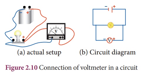
Note the positive (‘+’)
red terminal of the voltmeter is connected to the positive side of circuit and
the negative (‘–’) black terminal is connected to the negative side of the
circuit across a component (light bulb in the above illustration).
Exercise 2.5
A charge of 2x10⁴
C flows through an electric heater. The amount of electrical energy converted
into thermal energy is 5 MJ. Compute the potential difference across the ends
of the heater.
V = W/q that is 5x10⁶
J / 2x10⁴
C = 250 V
5. Resistance
The Resistance (R) is
the measure of opposition o ered by the component to the flow of electric
current through it. The opposition to the flow of current is caused in terms of
opposition to the flow of electrons by other electrons and the thermal
vibrations. Different electrical components o er different electrical
resistance.
Even the conducting
wires o er resistance to the flow of electric current through it. But, it is
very much negligible. Metals like copper, aluminium etc., have very much
negligible resistance. at is why they are called good conductors. On the other
hand, materials like nicrome, tin oxide etc., o er high resistance to the
electric current. We also have a category of materials called insulators; they
do not conduct electric current at all (Glass, Polymer, rubber and paper). All
these materials are needed in electrical circuits to have usefulness and safety
in electrical circuits.
The resistance offered
by a material at a particular temperature depends on the,
i. geometry of the
material and
ii. nature of the
material.
The SI unit of
resistance is ohm with the symbol (Ω). One ohm is the resistance of a component when the
potential difference of one volt applied across the component drives a current
of one ampere through it.
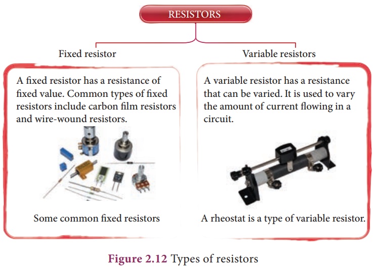
We can also control the
amount of flow of current in a circuit with the help of resistance. Such
components used for providing resistance are called as ‘resistors’. The resistors
can be xed or variable.
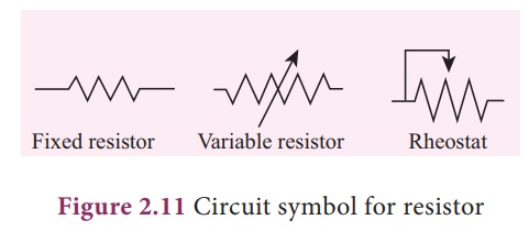
Fixed resistors have xed
value of resistance, while the variable resistors like rheostats can be used to
obtain desired value of resistance as shown in Figure 2.11.
6. Ohm’s law
Ohm’s law states that
electric potential difference across two points in an electrical circuit is
directly proportional to the current passing through it. That is,
V ∞ I
The proportionality
constant is the resistance (R) offered between the two points.
Hence, Ohm’s law is
written as,
V = R I (or) V = I R
Where V is the potential
difference across the component in volt(V), I is the current flowing through
the component in ampere(A) and R is the resistance of the component in ohm ( ).
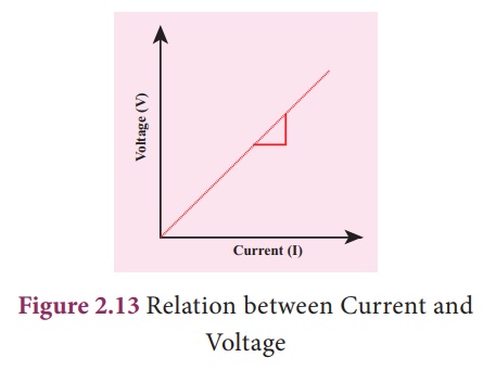
Any appliance connected
to the circuit o ers resistance. We can measure it by measuring the current (I)
owing through them and the potential difference (V) across them. Once we
measure these two quantities, we can compute R from the formula R=V/I. When we
plot a graph by taking current (I) in the x-axis and voltage (V) in the y-axis,
we get a straight line as shown in Fig 2.13. The slope of the line gives the
value of resistance (R)
Example 2.6
A potential difference
of 230 V applied across the heating coil drives a current of 10 A through it.
Calculate the resistance of the coil.
V = 230 V; I = 10A
R = V/ I that is 230/10
= 23
Related Topics