Chapter: Mechanical : Design of Transmission Systems : Bevel, Worm and Cross Helical Gears
Design procedure for Bevel Gear
Design procedure for Bevel Gear
17. Calculation of gear ratio (i) and pitch angle:
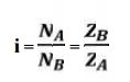
where, NA and NB = speed of the driver and driven respectively, and ZA and ZB = Number of teeth on driver and driven respectively.
18. Selection of material
Consulting Table 5.3, knowing the gear ratio i, choose the suitable material.
19. If not given, assume gear life (say 20000 hrs)
20. Calculation of initial design torque:
[Mt] = Mt . K. Kd
where, [Mt] = transmission torque
K = Load factor, Table 5.11
Kd = Dynamic load factor, Table 5.12
Assume K. Kd = 1.3 ( if not given)
21. Calculation of Eeq, [ϭb] and [ϭc]:
ü From table 5.20 Calculate Eeq
ü Calculate Design bending stress [ϭb]
[ϭb] = (1.4 Kbl/n.Kσ) σ-1, for one rotation [ϭb] = (Kbl/n.Kσ) σ-1, for both rotation
ü Calculate Design contact stress [ϭc] by [ϭc] = CB . HB. Kcl (or)
[ϭc] = CR . HRC. Kcl
where, CB CR = Coefficient of surface hardness from table 5.18
HB HRC = Hardness number
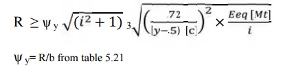
22.Calculation if cone distance (a):
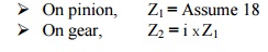
23. Select number of teeth on gear and pinion:
24. Calculation of module:
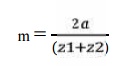
Choose standard module from table 5.8
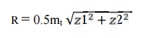
25. Revision of cone distance (m):
26. Calculate b, d1av, v and ѱy :
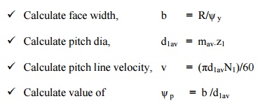
Calculate face width, b = R/ѱy
Calculate pitch dia, d1av = mav.z1
Calculate pitch line velocity, v = (πd1avN1)/60
Calculate value of ѱp = b /d1av
27. Selection of quality of gear:
Knowing the pitch line velocity and acosulting table 5.22, select a suitable quality
of gear.
28. Revision of design torque [Mt]: Revise K:
Using the calculated value of ѱy revise the K value by using table 5.11
Revise Kd:
Using the selected quality if gear and pitch line velocity, revise the Kd
value.
[Mt] = Mt . K. Kd
29. Check for bending:
Calculate induced bending stress,
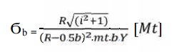
Compare Ϭb and [Ϭb].
If Ϭb ≤ [Ϭb], then design is safe.
30. Check for wear strength:
Calculate induced contact stress,
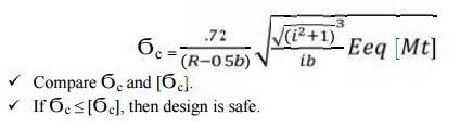
If Ϭc ≤ [Ϭc], then design is safe.
31. If the design is not satisfactory (ϭb > [ϭb] and / or ϭc > [ϭc] ), then increase the module of face width value of the gear material.
32. Check for gear:
e. Check for bending:
Using Ϭb1.y1 and Ϭb1..y1,
Ϭb2 = 
Compare Ϭb2 and [Ϭb2].
If Ϭb2 ≤ [Ϭb2], then design is safe.
f. Check for wear strength:
Calculate induced contact stress will be same for pinion and gear,
So,
Ϭc2 = Ϭc
Compare Ϭc and [Ϭc]
If Ϭc ≤ [Ϭc], then design is safe
Related Topics