Chapter: Civil : Design of Reinforced Concrete Elements : Limit State Design Of Footing
Design Problem, Important Question And Answer: Civil - Limit State Design Of Footing

2. Design
an isolated footing for an R.C. column of size 230 mm x 230 mm which carries a
vertical load of 500 kN. The safe bearing capacity of soil is 200 kN/m2.
Use M20 concrete and Fe 415 steel.
Solution
Step
1: Size of footing
Load
on column = 600 kN
Extra
load at 10% of load due to self weight of soil = 60 kN
Hence,
total load, P = 660 kN
Required
area of footing, - = _ /01. = _ 223433
= 5. 5_64
Assuming a square
footing, the side of footing is 7 = 0 = _ )5. 5 = 8. 94_6
![]()
Hence, provide a
footing of size 1.85 m x 1.85 m
Net upward pressure
in soil, : = ;__ _ = 175.3_BC/E,
__
< 200_BC/E,
Hence O.K.
+.<=_>_+.<=
Hence, factored
upward pressure of soil, pu = 263 kN/m2 and, factored
load, Pu = 900 kN.
Step
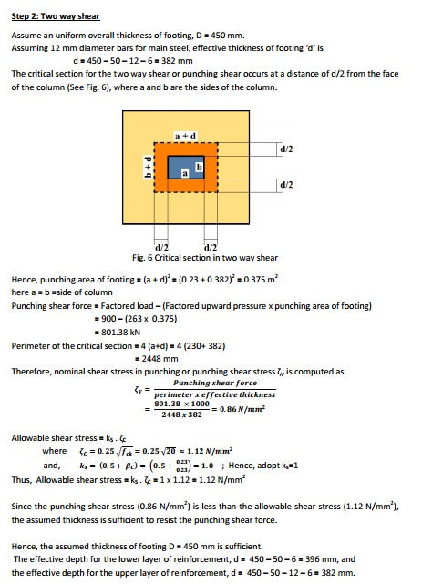
2: Two way shear
Assume an uniform overall thickness of footing, D = 450 mm.
Assuming 12 mm diameter bars for main
steel, effective thickness of footing 'd' is d = 450 - 50 - 12 - 6 = 382 mm
The critical section for the two way
shear or punching shear occurs at a distance of d/2 from the face of the column
(See Fig. 6), where a and b are the sides of the column.
Hence, punching area of footing = (a +
d)2 = (0.23 + 0.382)2 = 0.375 m2 here a =
b =side of column
Punching shear force = Factored load - (Factored upward pressure x
punching area of footing)
= 900 - (263 x 0.375)
= 801.38 kN
3.
Design an isolated footing for an R.C. column
of size 300 mm x 300 mm which carries a vertical load of 800 kN together with
an uniaxial moment of 40 kN-m. The safe bearing capacity of soil is 250 kN/m2.
Use M25 concrete and Fe 415 steel.
Solution
Step
1: Size of footing
Load
on column = 800 kN
Extra
load at 10% of load due to self weight of soil = 80 kN Hence, total load, P =
880 kN
Let
us provide a square isolated footing, where L=B Equating the maximum pressure
of the footing to SBC of soil,
�
+_�� =
���l
i.e., 99304 +_Z30_V5_2 =
4\3
![]()
On solving the above
equation, and taking the least and feasible value, B = 2 m
Hence, provide a
square footing of size 2 m x 2 m
The maximum and
minimum soil pressures are given by
T6PV = _ 93344
+_Z34_V5_2 =
453 X[64 < __250 6X[4
__�.
�.
![]()
T6LI = _ 93344
?_Z34_V5_2 =
8e3 6X[4 _ y _''''____�.
-.
![]()
Hence, factored
upward pressures of soil are,
pu,max = 345 kN/m2 and pu,min = 255 kN/m2
Further, average pressure at the center of the footing is given by
pu,avg = 300 kN/m2
and, factored load, Pu = 900 kN, factored uniaxial moment, Mu = 60 kN-m
Step
2: Two way shear
Assume an uniform overall thickness of footing, D = 450 mm
Assuming 16 mm diameter bars for main
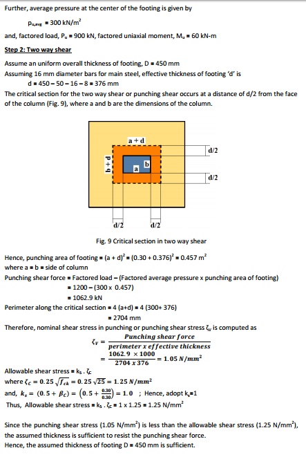
steel, effective thickness of footing 'd' is d = 450 - 50 - 16 - 8 = 376 mm
The critical section for the two way
shear or punching shear occurs at a distance of d/2 from the face of the column
(Fig. 9), where a and b are the dimensions of the column.
Hence, punching area of footing = (a +
d)2 = (0.30 + 0.376)2 = 0.457 m2 where a =
b = side of column
Punching shear force = Factored load - (Factored average pressure x
punching area of footing)
= 1200 - (300 x 0.457)
= 1062.9 kN
Therefore,
nominal shear stress in punching or punching shear stress ?V is computed as
Since the punching shear stress (1.05
N/mm2) is less than the
allowable shear stress (1.25 N/mm2), the assumed thickness is sufficient to resist the punching shear
force.
Hence, the assumed thickness of footing D = 450 mm is sufficient.
The effective depth for the lower layer of reinforcement,
, d = 450 - 50 - 8 = 392 mm, and the effective depth for the upper layer of
reinforcement, d = d = 450 - 50 - 16 - 8 = 376 mm.
Step
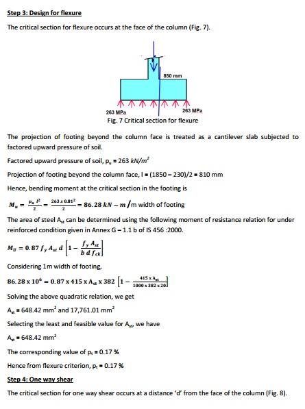
3: Design for flexure
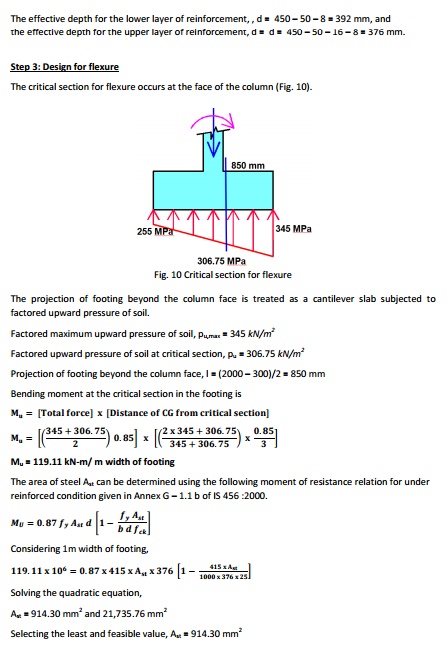
The
critical section for flexure occurs at the face of the column (Fig. 10).
The projection of footing beyond the column face is
treated as a cantilever slab subjected to factored upward pressure of soil.
Factored
maximum upward pressure of soil, pu,max = 345 kN/m2
Factored
upward pressure of soil at critical section, pu = 306.75 kN/m2
Projection
of footing beyond the column face, l = (2000 - 300)/2 = 850 mm
Bending
moment at the critical section in the footing is ��
Mu
= 119.11 kN-m/ m width of footing
|
Solving
the quadratic equation, |
|
|
Ast
= 914.30 mm2 and 21,735.76 mm2
Selecting
the least and feasible value, Ast = 914.30 mm2
The corresponding value of pt = 0.24 %
Hence from flexure criterion, pt = 0.24 %
Step
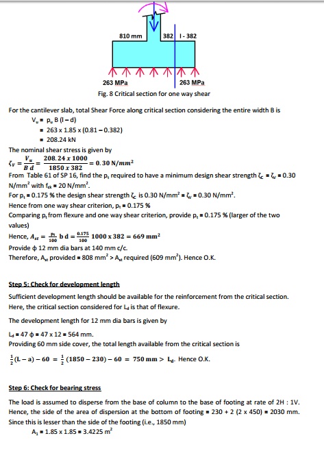
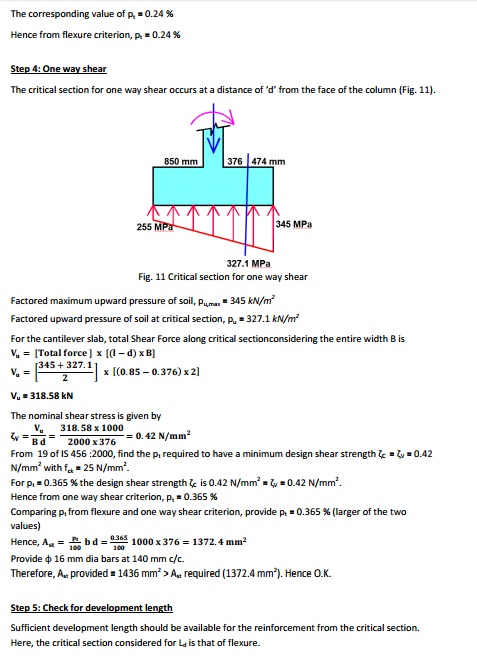
4: One way shear
The critical section for one way shear occurs at a distance of 'd'
from the face of the column (Fig. 11).
Step
5: Check for
Step 6: Check for bearing
stress
The load is assumed to disperse from
the base of column to the base of footing at rate of 2100H:1V. at he bottom of footing =
Related Topics